|
|||||||||
Build a Mirror Tester
|
|||||||||


|
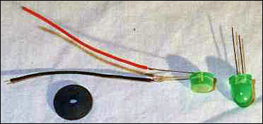
A Note on Polarity: The LED must be wired with the proper polarity to work. If you reverse the polarity, no harm will occur, but the LED will not light. Make sure the positive lead of the LED (called the anode) is connected to the positive side of the battery (usually a red wire). If your LED doesn't work, try reversing the connections to it. |
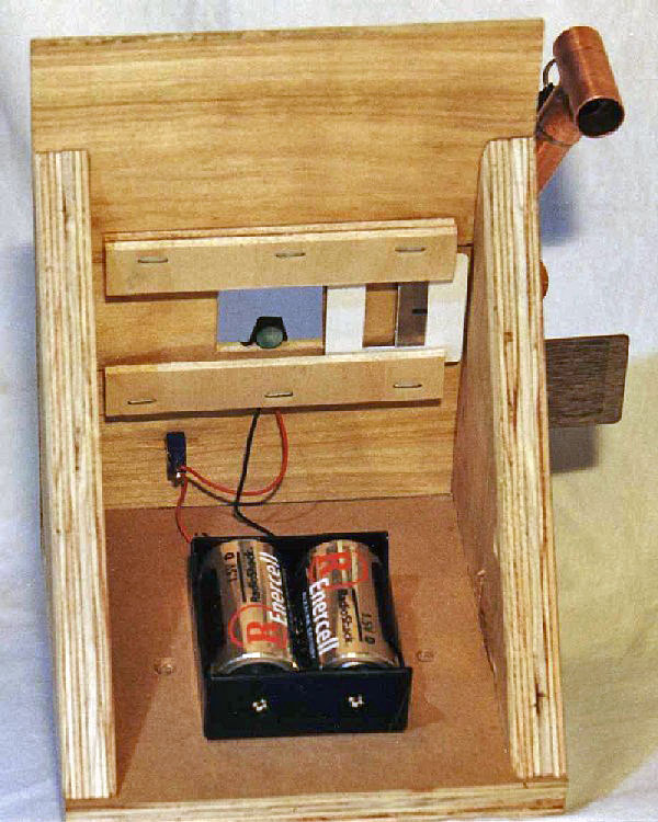
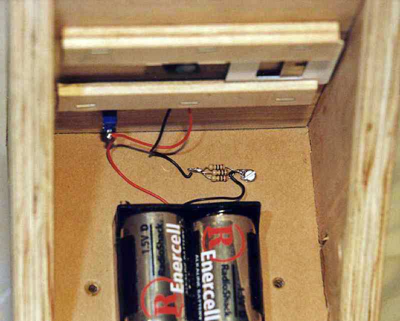
HOOKING EVERYTHING UP: The wiring is straightforward; you can refer to the schematic diagram at right and the photo above for guidance. Note that the 3.3 Ohm resistor is specific to the LED we used, you may need to use another value: See the calculations below. Make the 3.3 ohm equivalent resistor by twisting together the leads of three 10 ohm resistors and then soldering them. Solder the negative (black) lead from the battery pack to one end, secure this end under the screw, and then solder the black wire from the LED to the free end. This should leave two unconnected red wires, one from the LED and one from the battery pack. Solder one to each of the two switch terminals (middle and one side if your switch has three terminals).
Insert batteries and toggle the switch on. If the LED does not light:
- Check that all connections are well soldered.
- Check for polarity problems (see box above).
- Check that your batteries are good.
Mount your completed Test Head on the Stage with two screws, offsetting slightly away from the stage's adjustable foot. Congratulations! You have just completed building a fine tester which should give long years of good service.
USING ANOTHER LED: If you use an LED other than the one we used, you may have to use a different value resistor. This section will tell you how calculate the required value. The resistor is used to control or limit the current flowing in the circuit - too high a current can burn out a LED.
We used a Radio Shack part number 276-215 Green Jumbo Light Emitting Diode with 350mcd brightness and a peak emission wavelength of 565nm. (Note that this part is no longer available - see Page 4) We will use this part's characteristics in our example calculations.
You will need to know the Forward Voltage or Nominal Supply Voltage for your LED, and the Forward Current, which should be listed on the package.
First, calculate the Voltage that will be across the resistor:
VRESISTOR = VBATTERY - VLED= 3.0V - 2.8V = 0.2V
Here we used 3.0V as the fresh battery voltage (1.5V per cell) and the maximum forward voltage of the LED (2.8V) as listed on the package. You could be more conservative and use the typical forward voltage, which is listed as 2.2V.
Second, lookup the forward current of the LED, which will be the desired current through the resistor. (I is used by electrical engineers as the symbol for current).
ILED = IRESISTOR = 60mA = 0.060A
Here we again used the maximum value listed on the package. Again, the more conservative approach is to use the typical forward current of 40mA. We converted to Amperes from milliAmperes so that we would get Ohms of resistance in the next step.
Third, we use Ohm's Law (V = I * R) to calculate the desired resistance:
R= V / I = VRESISTOR / IRESISTOR = 0.2V / 0.060A = 3.33 ohm
Resistors come in only certain discrete, standard values, and you may have to round up or down to the nearest value - rounding up will slightly lower the current and is the conservative thing to do. Checking an electronics parts catalog, we see that 3.3 ohm resistors are made, as are 3.0 and 3.6 Ohm units. However, Radio Shack does not typically stock resistors smaller than 10 ohm. Since resistors are inexpensive items (about $0.50 for a 5-pack at Radio Shack, and less than a penney in 100 quantity mail order) we choose to use several 10 ohm units in parallel to get our desired value.
Equivalent Resistance of Resistors in Parallel:
REQUIVALENT = 1 / [ (1/R1) + (1/R2) + (1/R3) + ... ] = 1 / [ (1/10) + (1/10) + (1/10) ] = 1 / [ 3/10] = 10/3 = 3.33 Ohms
Using more conservative values will decrease the brightness slightly and increase the LED lifetime. Our LED cost less than $3, so we choose to push for maximum output at the risk that it will need to be replaced sooner. Our unit has been used by several club members for over a year with no ill effects noticed, and plenty of brightness for testing even in only slightly darkened rooms.
| Test Equipment Page Navigation |
ATM Index | Tester 1 Base & Stage | Tester 2 Head | Tester 3 Electrical |
| Test Equip. | Tester 4 After Thoughts | Tester 5 Parts | Tester Stand |