
Build an Adjustable Cradle
The primary advantages of an adjustable cradle are:
At the 2010 Stellafane Convention, our adjustable cradle design won an Innovative Component Award in the Mechanical Competition.
- Eyepiece angle can be easily adjusted. Most people like it pointing almost straight up for viewing near the horizon, and pointing sideways for viewing near the zenith, with intermediate positions used for viewing in between.
- Tube balance can be easily adjusted. This is advantageous if some of your eyepieces or optional accessories (like a camera adapter) are heavy.
- The tube can be easily removed from the cradle if necessary.
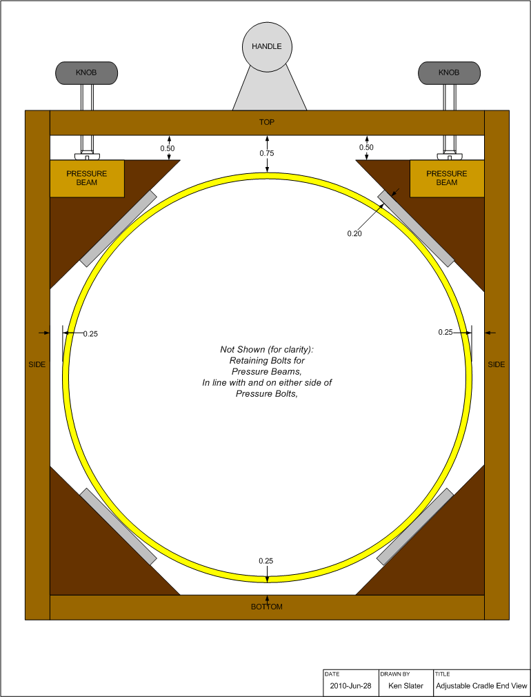
In our adjustable cradle, we will add eight 45° corner braces to the box cradle; they will be sized so that the tube rests on and is squeezed by them, not the sides of the box. The lower four are fixed; the upper four have adjustable pressure on them, so they can be loosened to adjust the tube and tightened to hold the tube firmly in place. The additional work needed to do this is small, and the fixed braces stiffen the box as an added benefit. All this is done with simple straight cuts that are easy to make.
We will use a mixture of ½ and ¾ inch plywood in our cradle to keep the weight down. We realize this might not be the most economical way to build this; if you buy a single sheet of ¾ inch plywood you may have enough material to build the entire mount - so feel free to use ¾ inch everywhere, adjusting the dimensions as necessary.
Design & Layout
Cradle length is discussed on the previous page (We will use 12 inches, based on 2 times our 6 inch primary mirror size). Here we will concentrate on the box and corner brace dimensions. The key starting point is your tube outside diameter (for us, it is 8¼ inches).
The Box: We are using ½ inch N-N birch plywood, you can certainly use ¾ if your wish. The box part widths can be calculated as follows:
Side Height = Tube OD + ¼" bottom gap + ¾" top gap +
              ( 2 × Plywood Thickness )
Top & Bottom Width = Tube OD + ( 2 × ¼" side gap )
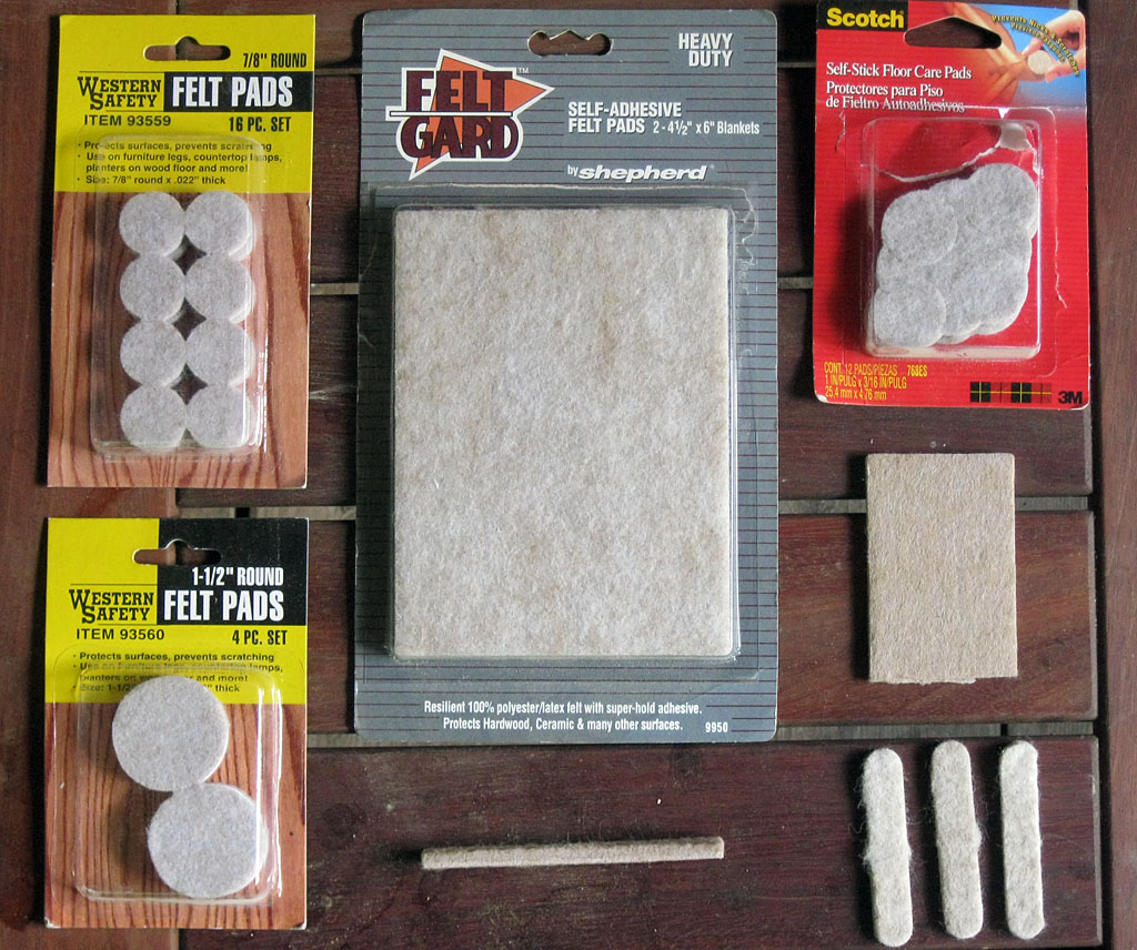
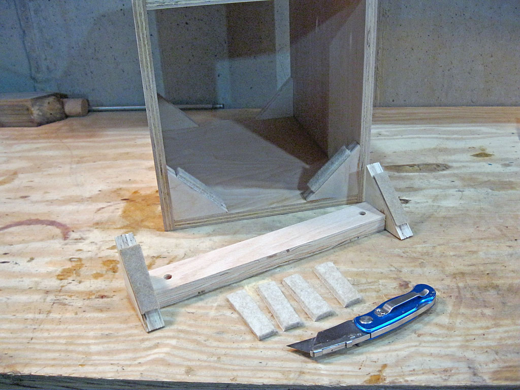
Felt Pads: In the furniture feet and glide section of a hardware store or home center, you should be able to find self adhesive thick felt pads. Most commonly these come in rounds, but there are often strips or 4 × 6 sheets available also, which is what we used, cutting out 2 inch by ¾ inch pads from the sheet. The package we bought claims the thickness is 0.22 inches; when measured at home we got between 0.20 and 0.18 thickness. For our design, we used a value of 0.20 inches to size our triangles.
The Triangles: We need to make eight triangles. We are using ¾ inch N-N plywood as a wider bearing surface is desired to press on the tube. Allowance needs to be made for the felt pad thickness. The easiest way to size the triangles is to make a scale drawing of the cradle with a ruler and compass. You only need to draw one quarter of the cradle, from the tube center out to one corner. Once you have the tube outside diameter and a side and bottom drawn in, draw a 45° line tangent to the tube. Then draw a parallel line to this 0.20 inches away (the pad thickness) from box side to box bottom - this defines your triangle.
You can cut the triangles by making a rectangle whose height is the height of one side of the triangle and long enough to hold eight of them, including allowance for your saw kerf. Measure out and cut one triangle at a time so that saw kerf thickness does not accumulate and result in ever smaller triangles as you cut. Use a clamp to hold the long part of the rectangle, and hang enough off your workbench to cut. The first cut will be a 45° cut, the second cut will be a 90° cut, and so on.
Four of the triangles need to be notched to accept the pressure beams.
If you don't mind making curved surfaces, curving the triangles to match the tube is an improved way to build them. See this example from Carlucho Paris.
The Pressure Beams: Each pair of upper triangles are connected by a pressure beam made out of ¾ inch plywood. They are the length of the tube cradle. They should be as wide as possible without projecting beyond the triangles and hitting the tube; for our 8¼ inch tube we choose a width of 1½ inches. Adjust to your tube size as necessary.
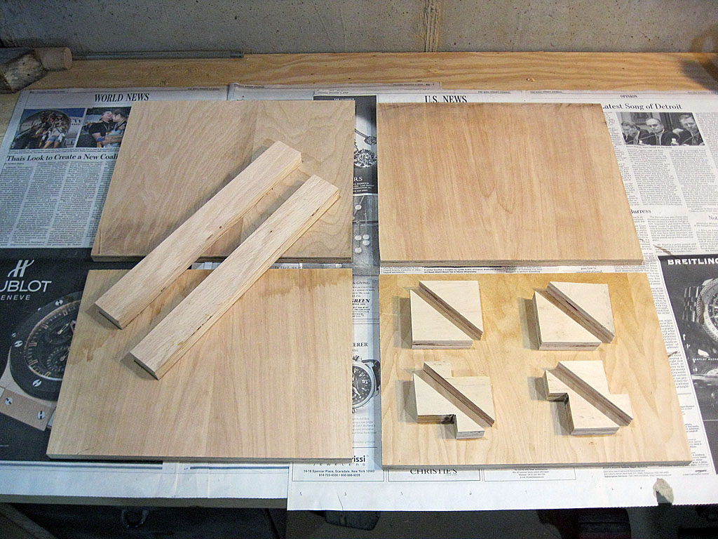
Cutting & Drilling
Cut out the parts described above: [1] Top, [1] Bottom, [2] Sides, [2] Pressure Beams, [8] Triangles ([4] with a notch). It is important that the cradle box be square, or else your telescope might wobble or move at an angle in altitude, so cut as carefully as you can, keeping the saw perpendicular to the surface.
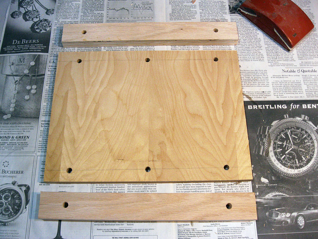
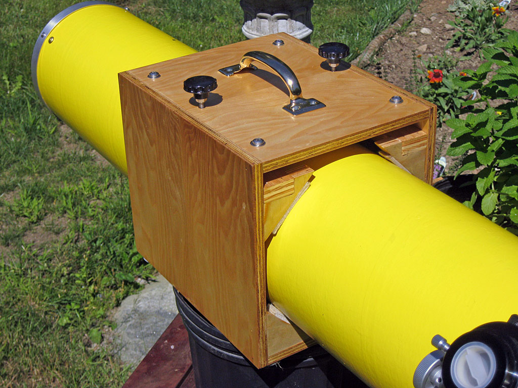
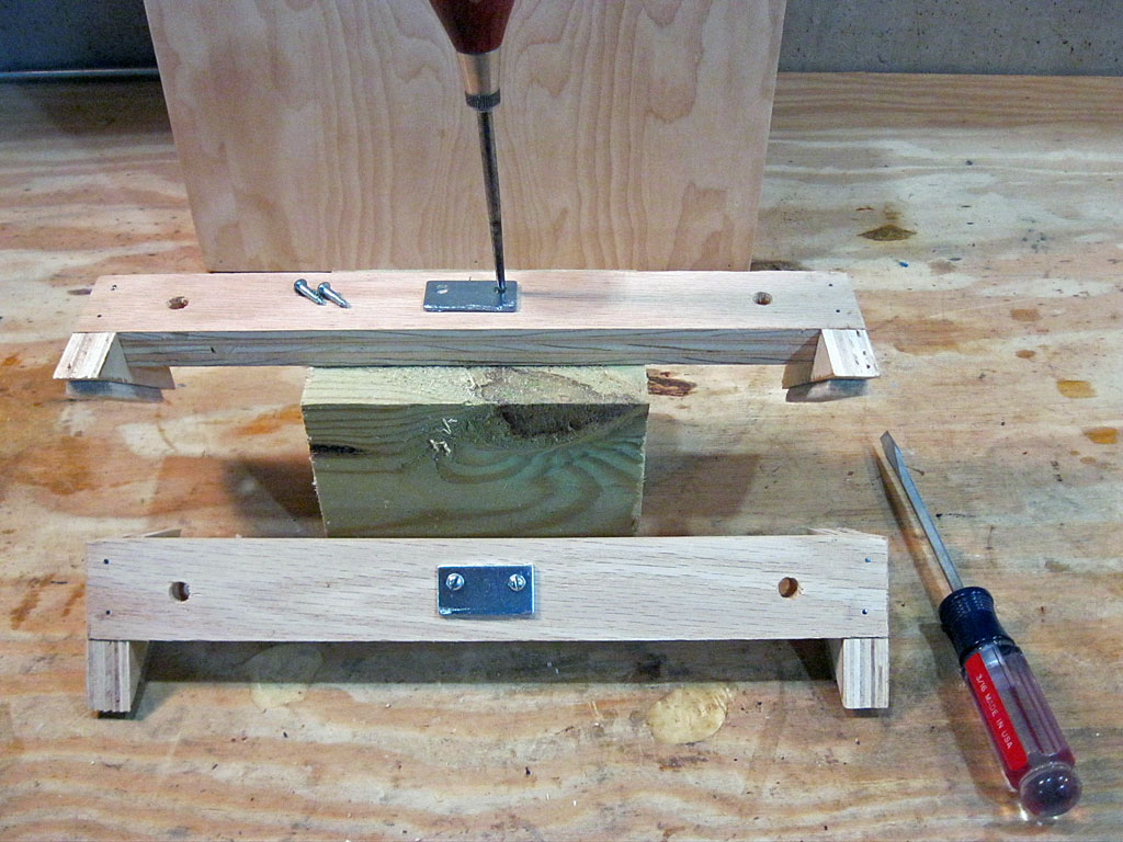
The top is drilled with 5/16 inch holes and the pressure beams are drilled with 3/8 inch holes. There are six holes in the top, and two holes in each pressure beam, as shown in the photo at right. Again, keep your drill square to the surface of the part you are drilling so that the bolts that will pass through these holes will not bind.
All holes are centered on the pressure beams; since our pressure beams are 1½ inches wide, the holes are ¾ inches from the edge of the beams and the top.
The four holes near the ends are 1½ inches in; the two center holes in the top are centered.
Hardware
To assemble the cradle box, and attach the triangles to the box and pressure beams, we will use carpenters glue and 1¼ × 18 wire brads, which we call finishing nails in the remainder of the text. These are thin enough so that they will not separate the plies of the plywood when nailed into an edge.
We will use the following hardware for the cradle assembly, and purchase stainless steel parts when possible to avoid rust:
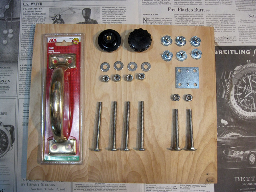
- [4] ¼-20 3 inch long Pan Head Bolt - fully threaded (retaining bolts for pressure beams)
- [2] ¼-20 2 inch long Carriage Bolts - fully threaded (pressure bolts for pressure beams)
- [6] ¼-20 Tee Nuts
- [4] ¼ inch Washers
- [2] ¼-20 Hex Nuts
- [4] ¼-20 Lock Nuts
- [2] Knobs for ¼-20 shafts (Found in "Small Parts Drawers")
- [2] Mending Plates (Carriage Bolt head presses on these)
- [1] Large metal handle (for carrying cradle and tube.)
Note that bolt lengths given are sized for our 8¼ inch tube; these will have to be adjusted for other sized tubes.
Wooden Parts Assembly
It is usually easier to sand flat parts rather than assembled parts, so we will sand all parts before assembly to make finishing easier later on.
In the underside side of the top, press or hammer in six Tee Nuts into the drilled holes.
Now assemble the cradle box using carpenters glue and a few finishing nails to hold the parts in place while the glue dries. We used three nails on each joint, starting the 6 nails on each side piece before assembly. The first joint is the hardest to manage when assembling, start with a side and top, spread glue on the edge of the top (remember the tee-nuts are on the inside of the box), and have the bottom nearby. Now with the top standing on it's non-glues edge, align the side to the top and set it on the glue. Then with a free hand (you have at least four hands, right?) place the bottom on edge, at right angles to the top, to support the side piece while you do final alignment and nailing of the glued joint. Slightly countersink the nail heads to just below the surface. Wipe off any excess glue with a damp rag as you work. With the first joint done, you can attach the bottom to the installed side, then flip this U-shaped assembly over and install the last side.
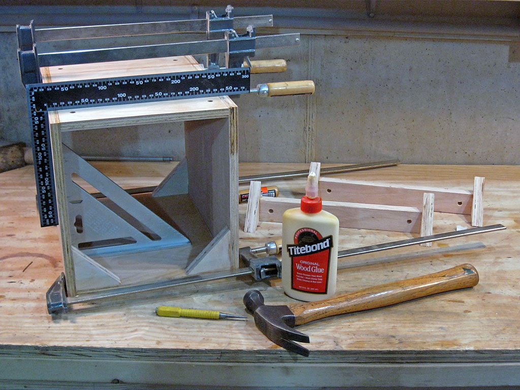
Use a square to make sure the box is square - nudge it into square if it is not. Now nail and glue the four lower triangles into the bottom of the box, which will also help keep the box square. We used two nails through the hypotenuse of each triangle, one into a side, the other into the bottom.
If you have clamps, you might want to clamp the box sides together until the glue sets. If you don't, you could rest the box on a side, and pile some heavy objects on top of it. Do a final check for squareness and then let it dry, usually 24 hours for most glues.
Assemble the pressure beams to the notched triangles, again using finishing nails and carpenters glue.
Do a final wipe up of glue that has seeped out of the joints, and take the rest of the day off!
Hardware Assembly
We will now do a test assembly of the hardware parts, and make sure everything fits and works well. Then we will disassemble the hardware and finish the wooden parts. We will not attach the handle at this time - we are not concerned about it's fit.
Felt Pads: Cut eight ¾ × 2½ inch self adhesive felt pads from a felt sheet. Attached to the center of each or the eight triangles. Note: After about a week of use in hot summer weather with the tube stored vertically, the adhesive on the pads failed, and the tub dropped about 2 inches into the rocker box. We now recommend you use two small brads in each pad, at the ends where they will not contact the tube, to secure these pads to the cradle.
Mending Plates: Attach a mending plate in the center of each pressure beam, so that the pressure bolt head will press against it. We cut a single square mending plate in half for this. We suggest using a block of wood to work on, lifting the beam off the triangles and providing a flat, firm work surface.
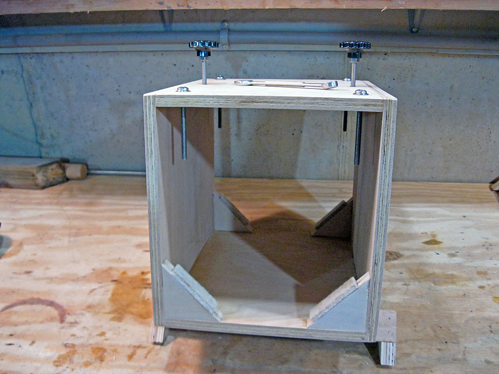
Bolts in the Top: Check your two carriage bolt heads, some have embossed lettering on them that should be filed off leaving a smooth, rounded head (this time, our bolt heads we unblemished by lettering). Then screw them fully into the two middle tee nuts from inside the box, so that they stick up above the box (no need to tighten them). Then thread a hex nut about an inch onto the projecting bolt. Next screw on your threaded knobs, and tighten the hex nut against them to hold them tight to the bolt. If you can't find threaded knobs, try buying some "radio knobs" at Radio Shack or another electronics distributor - ¼ inch shafts are standard, and they will have set screws to hold them tight.
Now place a washer on each of the four pan head pressure beam retaining bolts and screw them down from the top into the box and tighten.
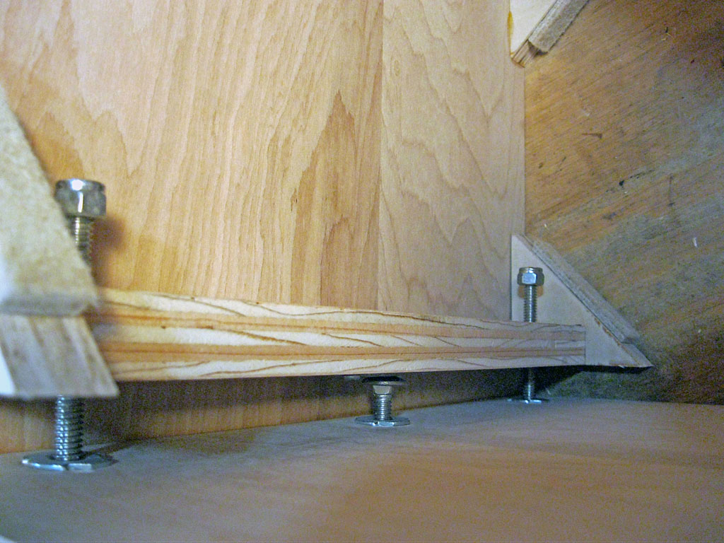
Install Pressure Beams: Now install the pressure beams onto the pressure beam retaining bolts. This is likely were you may have some fit problems - they should slide freely over the bolts. The first beam we installed was perfect - it slipped on easily and moved freely. The second beam was a different story, it would not even fit on. We had to straiten one bolt (the tee nut was not seated fully) and then enlarge one pressure beam hole a lot, and the other just a very little, until we got good free sliding action. It looks like on the one hole that needed a lot of enlargement, we did not drill very accurately. And now you know we do test fits before finishing! Screw lock nuts onto each of bolts to prevent the pressure beams from falling off. Screw them on until the bolt is flush with the top of the nut, firmly held by the plastic locking part.

Insert Tube and Test: With the pressure bolts fully released, You should be able to slide your telescope tube into the cradle, primary end first. This requires a little juggling, as you need to hold the pressure beams up (maybe 4 light springs between the lock nuts and beam would be a nice improvement?). Roughly center the tube in the cradle, and apply gentle pressure by tightening the pressure knobs - you might be surprised at how little it takes to grip the tube, and it is possible to distort the tube with too much pressure - so go easy! Then release the pressure slightly and make sure you can rotate the tube and slide it up and down a bit. If this does not work, check clearances and make adjustments as necessary. Make sure the retaining bolts are not so long as to touch the tube. Congratulations, you have made a very nice adjustable cradle. Just a few simple things left to complete it.
Finishing Up
Remove all the hardware except the tee nuts and felt pads (if you want to remove the felt pads for finishing, you will either have to cut new ones for the final assembly or use a strong double sided tape to reattach the old ones). Do a final sanding and finish the wooden parts with paint or some other waterproof sealer (we are using clear satin polyurethane).
Once the finish is dry, reassemble the hardware. Attach a handle to the top center of the cradle. A picture of the completed cradle is at the top of this page.
Your adjustable cradle is technically done - but to be truly complete it needs altitude bearings. This is the topic of our next page...
Previous: Tube Cradle
Next:
Altitude Bearings
Back to the Build a Dobsonian Master
Index