|
by Walt Hamler
664 Tuscora Drive
Winter Springs, FL 32708
Go to Walter Hamler's Astrophoto Page.Soon after finishing a 10" Dobsonian earlier this year, I came to realize
that I missed the tracking ease of an equatorial mounted telescope. I knew about the existence of the "dob
tracker platforms", but had never looked closely at the construction design and requirements. Checking the ATM
resource lists on the web led me to a site by Warren Peters that provided both in very precise instructions.
Warren's site referenced platforms by David Shouldice and Chuck Shaw. Basically I took elements of each and came
up with my platform.
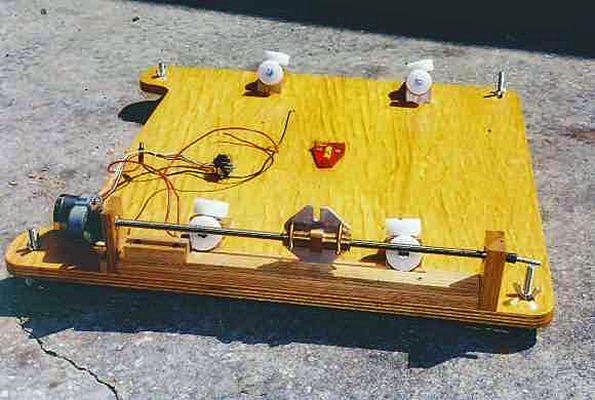
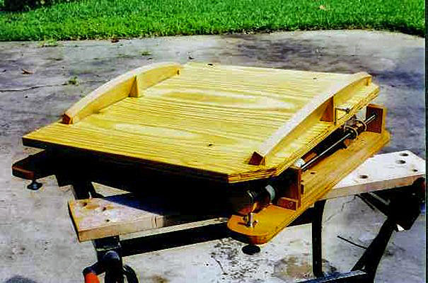
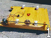
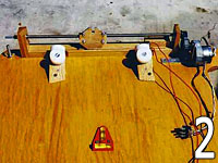
The base unit (Image 1) is about 2 feet per side, made from 3/4" AB plywood with several
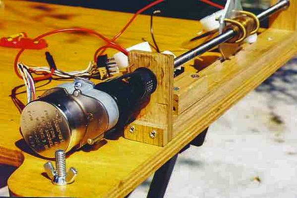
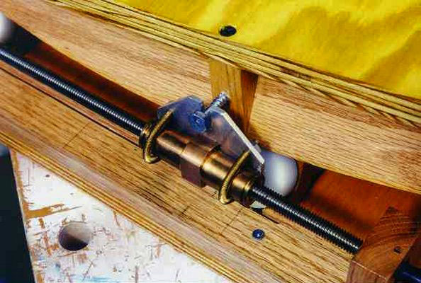
coats of polyurethane. The lead screw (Image 2) unit was purchased from Herback and Rademan, a New Jersey
company that specializes in surplus equipment. One of their catalog supplements had a 3/8 - 16 lead screw with a
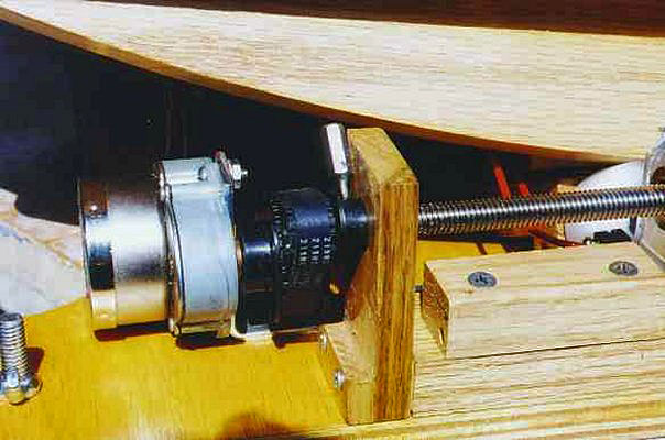
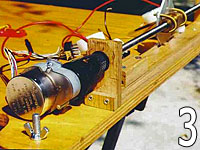
stepper motor, bearings, and bronze follower nut that was perfect for a platform. I opted for a different motor
(Image 3), one that had a 1:70 gear reduction built in. H&R also had a stepper motor controller kit that I had
calculated would allow me to run the motor over a fairly wide range of speeds. That proved to be an error on my
part as the motor would not run at the final output speed of 2 rpm required. I could only get a max of 1.25 rpm
before resonance problems would cause the motor to lock up. My solution was to order a 2:1 cog wheel and belt
set from Small Parts, Inc. of Miami, FL. This allowed the output speed of the motor to be doubled to give the 2
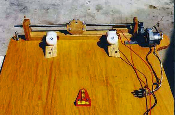
rpm lead screw rate required. The bearing blocks to hold the lead screw and bearings are made from 1x2 red oak
strips available at Home Depot, etc.
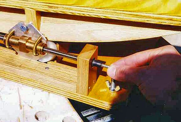
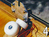
The drive plate (Image 4) contacts a micro switch at the end of the travel that turns off the
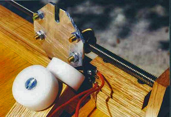
power from the 12vdc source. Also seen in the pictures are the Delrin wheels attached to the bearing supports. I
decided to make these supports from the same red oak strips as before, rather than cutting them from a single
piece. I'm really not known for my carpentry skills, even though my father was a master carpenter. My brother, a
master machinist, cut the wheels from round Delrin stock that turned out very nice and very inexpensive as well.
I had looked into roller blade wheels as several web sites mentioned, but the 8 wheels would have cost over $90
with bearings. The Delrin stock was less than $20, and my brother was gracious enough to do the work gratis!
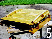
The runners (Image 5) were also made from the red oak material. I first cut them to shape
with a saber saw attached to a radius rod to give the correct curve. I then touched up that cut with a router
attached to the same radius rod. I then hand sanded lightly. Three triangle supports were added to each runner,
then both pieces were run through a table saw set to give the correct angle for my Central Florida location,
28.5 degrees. A touch up with a belt sander and the runners were attached to the base top at the computed
separation. An interesting aside here. The trigonometric formula that Warren Peters provided in order to
calculate all the proper dimensions were interesting for this old codger. I graduated from high school in 1961,
and trig was my last math class prior to graduation. Suffice it to say that I had to do some brushing up on my
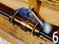
trig skills. However, when all was said and done, the complete unit works very nicely. At the beginning position
(Image 6) the angle of the top platform looks a little steep, but both my dobs sit nicely and with no tipping
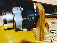
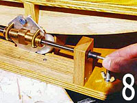
tendencies noted. After about 45~50 minutes the drive plate switch turns off the power, then the setscrew (Image
7) on the lead screw cog wheel is loosened, allowing the other end of the lead screw to be turned by hand to
reset (Image 8) the drive to the beginning position.
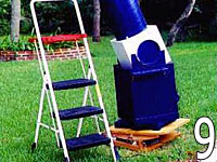
My 10" dob weighs about 85 pounds complete, but sits on the tracker very nicely. It does
raise the eyepiece about 6 inches from normal, requiring a step ladder to be ready for stars (Image 9). Initial
use has shown that the tracker will keep an object in the center of a 7.5mm fov, about 230x, for probably the
duration of the lead screw at least. As I'm not doing any astrophotography these days, I'm totally satisfied
with the unit's performance!!
Thanks Warren Peters and others!!
|