Build a Mirror Tester
A Foucault or Knife Edge Tester and Ronchi Tester
Page 1: Base & Stage
This page describe how to build a Slitless, Moving
Source Foucault1 Knife-Edge Tester. Provision is made to easily remove the knife edge
and replacing it with a Ronchi grating, making a Ronchi2 Tester. The tester is made
from common parts easily available from home centers, hardware stores and the electronics shops. The tester
is pictured with a $10 import dial indicator, which is a mail
order item. Alternative Measuring Techniques which are equally good are described
if you do not wish to use a dial indicator.
SLITLESS: In a slitless tester, a single knife edge is used to "cut" the illumination
source and the viewed image. This is a recent innovation that works quite well. It eliminates the need to make
a precision pinhole or slit, and automatically makes the source and viewing knife edges parallel (because they
are the same edge!).
MOVING SOURCE: Historically, light sources were bulky and hot. You can
see kerosene lamps being used in early testers in the Amateur Telescope
Making books. Early electric bulbs were also big and hot. Therefore, in the early testers the light source
was fixed with respect to the moving knife edge. Today, we can use battery powered miniature flashlight bulbs
or cool Light Emitting Diodes (LEDs), and the illumination source can ride on the moving stage with the knife
edge. Keeping the source to knife edge distance small is better, especially for fast (low focal ratio) mirrors,
and moving source testers do this well.
DESIGN NOTES: The tester has three major parts: the Base, the moving Stage, and the
test Head, which is attached to the stage. Building the tester in three distinct parts makes construction
(and describing the construction,) easier. Have a separable head makes it easier to experiment with other optical
test configurations.
Like the testers described in [Texereau84] and
[Berry94], our tester stage slides on Vee-blocks along a pipe
for precise and smooth motion along the optical axis. To move the knife edge across the optical axis, the stage
is rotated about the pipe, using an adjustable leg.
FEATURES: Optional alignment aids are provided. The short pipe on the left side of the head can be
rotated to the center of the viewing window, and a small flashlight (shown) or laser pointer can then be used
as a bright source to initially align the mirror with the tester. The large flat area surrounding the viewing
window serves as a target surface for the reflection during initial alignment. This is very handy when working
alone.
The knife edge (shown) and a Ronchi grating (not shown) can be mounted in standard 2" x 2" slide frames and
easily and quickly moved into position in front of the viewing window and light source.
A high-brightness green Light Emitting Diode (LED) is used as a light source. Its green light is in the center
of the visible spectrum, and it is cool and small and easily positioned close to the knife edge. Its low power
use means the batteries should last for many mirrors.
An inexpensive Dial Indicator is used to read stage displacement.
This item costs less than $15 by mail order, and makes reading stage positions easy. If you don't wish to use
a dial indicator, alternative methods are described.
A tape measure attachment point is provided, to make radius of curvature measurements easier. Combined with
the optional tape measure attached to our mirror stand, initial setup should be much easier than trying to hold,
measure and move individual components.
CONSTRUCTION: Building the Base
Start from the bottom and build up, making the Base, then the Stage and finally the Head. The
basic building material is 3/4" plywood. The tester shown in the photographs is made out of MDO plywood, which
has one surface veneer made of hardboard . You can use any type of plywood that is flat and has no large knots
or voids. Assemble wood parts with yellow wood glue ("Carpenters' Glue") and screws.
Drywall Screws are thin (helps to prevent splitting the plywood),
grab well, and have flat heads; they were used exclusively to build this tester. You might want to clamp any
plywood that is being screwed near the edge to help prevent splitting.
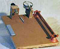
BUILDING THE BASE: The base shown at left is a square of plywood with three stick-on
felt feet - one can be seen at the front center. At the far left is a
Teflon™ pad for the adjustable foot of the stage to slide
on. The left block holds a lead screw to push the stage, the right block holds a dial indicator to measure the
stage's movement, and between them is a spring to pull the stage back against the lead screw. On the far right
is a 1/2" copper pipe on which the stage both slides and rotates. Refer to the
Base Plans for dimensions and positions for the parts of the
base.
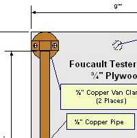 Dimensioned Base Plans
Start by gluing up the two pieces of the plywood for the Lead Screw
Block; when dry sand them smooth, drill the 5/16" hole for the lead screw and hammer a
Tee-Nut into each side. Get a 1/4"-20 by 3"
Carriage Bolt and sand or file its head smooth if there
are any imperfections. Then thread it into the Tee-Nuts - this may
require that one nut is unseated slightly - the result should be a smooth, wobble-free motion. A
Radio Knob is attached the open end of the bolt. Mark the block location
on the base, drill pilot holes, and glue and screw the Lead Screw Block to the base. Using an awl, poke a hole
for the cup hook next to the Lead Screw Block and screw in a small cup hook, with the opening facing outward.
Cut, drill and install the gauge block next if you will be using a
Dial Indicator; omit if you will be using the
Alternative Measuring Technique. The exact size and location may need to be adjusted
for your dial gauge, and the plans omit some details because of this. You may want to mark the general location
of the Gauge Block on the base, but delay mounting it until you have built the Stage. The
Dial Indicator should be mounted to contact the edge of the Stage,
and indicate a full 1" of motion over the full travel of the lead screw. 1/4"-20 hardware is used to attach
the indicator to the block. The block is glued and screwed to the base.
The 1/2" pipe is 10" long which yields a 9" sliding area after allowing for clamping. Copper water pipe was
used as it is easy to cut and has a smooth surface for sliding the Stage along - other smooth metal pipe or
rod could be used. It is held in place by copper Van Clamps, which
make mounting it rigidly easy. Wooden split blocks could be substituted if desired. Cut the pipe to length,
and use it to help position and mount the clamps. Then mount the pipe. Try to keep the pipe, lead screw and
dial indicator all parallel.
Finally, a few stick-on components. The adjustable leg on the stage needs a smooth, low friction surface
to slide on, and Teflon is ideal. We used 1" x 4" Teflon
Furniture Sliders. If you can't obtain Teflon, try to find a smooth, slippery plastic, such as Ultra High
Molecular Weight (UHMW) plastic. If you are really having trouble finding material, some plastic water or milk
jugs are very slippery and although thin, might be used. Attach three 1" diameter self-stick felt feet to complete
the base construction.
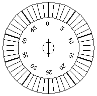
ALTERNATIVE MEASURING TECHNIQUE: If you do not wish to use
a dial indicator, you can use a dial scale on the lead screw to make measurements ([Berry94]
uses this technique).
A 20 turn-per-inch lead screw moves 1/20" or 0.05" per revolution. If you make a dial scale
for the lead screw and divide it into 50 equal divisions, each division then rep- resents 0.05"/50 = 0.001"
of motion. One way to do this is to make a 2" diameter disk from stiff cardboard with a 1/4" hole in the
center. Draw your own, or click on the dial at above, print the dial image and glue it to stiff cardboard.
With the carriage bolt screwed through the lead screw support block, screw on a 1/4"-20 nut and then a flat
washer. Slide your cardboard dial on, then the radio knob. Tighten the radio knob to the shaft, and then
tighten the 1/4"-20 nut against the washer, dial and knob - this should hold the dial scale firmly in place
by friction. Finally, you will have to make a pointer out of stiff wire or thin metal, so that markings
on the dial can be read. Since the dial will be moving in and out, a straight edge parallel to the lead
screw and just clearing the dial is best. Don't worry about "zeroing" the dial scale - the readings you
take will be relative to each other - absolute positions are not important.
This page was created in March 1999 when 640x480
monitors were still in widespread use and 800x600 monitors were
just starting to get popular. Hidde van Dijk noticed the dial
above was very low resolution two decades later, and kindly
provided high resolution images in three formats, which you can
download. As a bonus, not only were face dials provided, but
also an edge dial if that is what you would prefer. Thanks
Hidde!
Downloads:
FoucaultTesterDial.pdf FocaultTesterDial.png
FoucaultTesterDial.svg
CONSTRUCTION: Building the Base
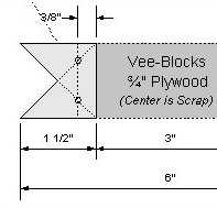 Dimensioned Stage Plans
BUILDING THE STAGE: As shown in the photographs, the stage is quite simple: A rectangle
of 3/4" plywood, two Teflon surfaced Vee-Blocks, a cup
hook for the spring, a pair of Tee-Nuts, a
Carriage Bolt and a Radio
Knob for an adjustable foot which tips the stage and will rotate the knife edge through the light path.
Start by cutting the 6" x 9" plywood rectangle as shown in the
Stage Plans. Locate and drill a 5/16" hole for the
Tee-Nuts, and hammer one into each side. Make an adjustable foot from
a 1/4"-20 x 3" Carriage Bolt and
Radio Knob, in the same way the Lead Screw
was made for the Tester Base (above). Use an awl to make a starting hole, then screw in a small cup hook.

The Vee-Blocks are now cut. As indicated on the plans, cut out a 1" x 6" piece of 3/4" plywood,
and mark it for cutting a Vee block at each end. The 6" length is long enough to clamp it while you carefully
cut the Vees; once done you can then make the easier, straight top cut to separate each block from the work
piece. Drill two 1/8" pilot holes in each Vee-Block. Then carefully glue and screw them to the edge of the Stage
as shown in the photographs (you may want to clamp the stage plywood to help prevent splitting near the edge).
Finally, you should attach two squares of Teflon Furniture
Sliders to each Vee-Block; we used 24mm squares for this. This completes the Stage.
Assembling the Base and Stage:
Hook a 2" long spring to the cup hook on the stage, then place the Vee-Blocks of the stage on
the pipe of the base. Hook the other end of the spring onto the cup hook on the base. The stage should be pulled
firmly back against the lead screw and dial indicator. Using the lead screw, it should have at least one inch
of smooth, jerk-free travel. The position should be able to be read off the dial indicator. The adjustable foot
of the stage should ride smoothly on the Teflon pad on the base, and it should be possible to rotate the stage
a few degrees about the pipe using the adjustable foot.
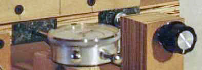
The close-up photograph at right shows wear pads on the stage edge for the lead screw and dial indicator.
They are cut from glossy countertop laminate samples that are commonly available at home centers or hardware
stores. They are attached with double sided carpet tape (Do not use double sided foam filled
tape - the "squish" of the foam is not acceptable in this application). An appropriate glue, such as contact
cement, can also be used.
You now have a solid, smooth linear motion stage and you can measure its motion to about
0.001" over a range of 1". The slight rotation about the pipe, controlled by the adjustable leg,
will let you move a knife edge or Ronchi screen through the reflected beam of a mirror. Continue
by building the Tester Head on Page 2. (Illumination and electrical
details are presented on Page 3.)
1Jean Bernard Leon Foucault invented the knife-edge test circa 1859.
2Vasco Ronchi invented the Ronchi test circa 1926.
|