
The Ground Board
& Final Assembly
The Ground Board is a simple piece of plywood that hold the feet, azimuth bearing pads and pivot in place. Because the pads are place directly over the feet, there is essentially no vertical load on this part; it only has some small loading in holding the parts in place horizontally. Therefore it can be made ½ inch plywood (which we will use) and have quite a bit of wood removed, as in our triad design without failing. You can choose to make the traditional circular ground board if you wish, and you can use ¾ inch plywood for either design.
Design & Layout
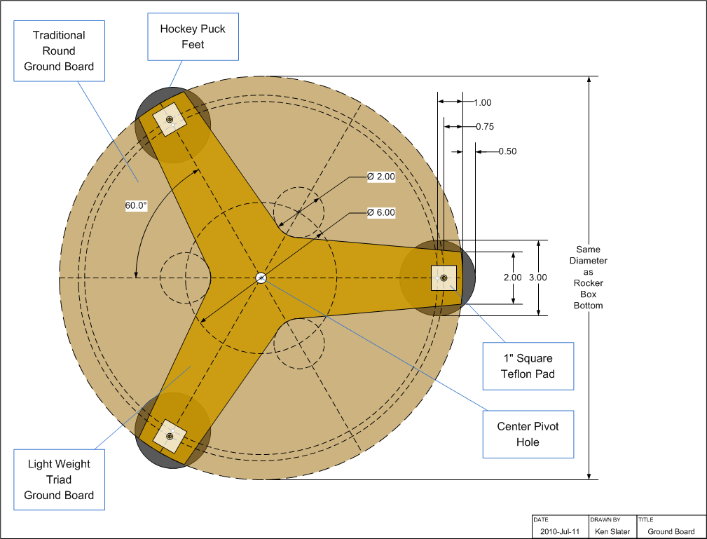
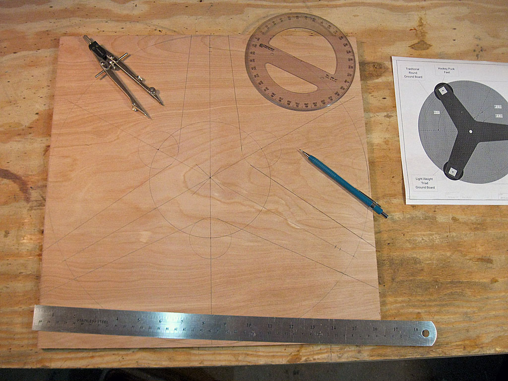
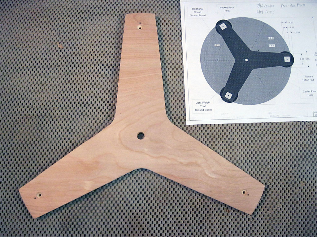
Start with a square of plywood that is slightly larger than your rocker box bottom (our Rocker Box has a 16 inch bottom, therefore we will start with a 16¼ inch square of ½ inch plywood). Draw a circle of the same size as your rocker box bottom on the plywood. If you want to make a circular ground board, this is the line you will cut and shape to. If you would rather make mostly straight cuts, you can layout our triad design, shown in the diagram. We used a hole saw to make rounded corners near the center, you could make them straight and acute if your wish. In either design, the holes for other parts are in the same place on the diagram.
Now draw three diagonals through the center, spacing them 120° apart so that you end up with six wedges of 60° each. These lines will be used to space the feet and pads around the circumference.
We recommend using hockey pucks for feet - they are weatherproof and large enough to provide a good stable footing. Hockey pucks are 3 inches in diameter and 1 inch thick. We need to mark the three holes for them 1 inch in from the edge, and therefore the hockey puck will stick out ½ from the ground board and rocker box.
We are using 1 inch square Teflon pads. We want them them inset ¼ inch from the edge, so we mark their location ¾ inch from the edge. If you are using a different pad size, adjust the hole location accordingly.
The center pivot bolt will pass through a 3/8 inch tee nut. Drill out a hole in the center for it; ours was 7/16 inch in outside diameter.
If you making the round ground board, layout is done. For the triad design, we need to mark the additional holes and cuts. We used a 2 inch hole saw to make the inner radius on the arms. Use your compass to draw a circle of 6 inch diameter; the 2 inch hole centers are on this circle where they cross the 60° lines that do not have feet or pads on them. We also need to mark one inch on either side of the line that do have feet and pads on them at the outermost circle - this is the width of the triad arms. You can then draw tangent lines to mark the straight arm cuts. This triad design can be adjusted to your taste, and to the size of hole saws you may already own. You can also make this with all straight cuts if you wish. Just keep the central hub about 5 inches in diameter, and the arms about 2 inch wide, or larger, and you will be fine.
Drilling & Cutout
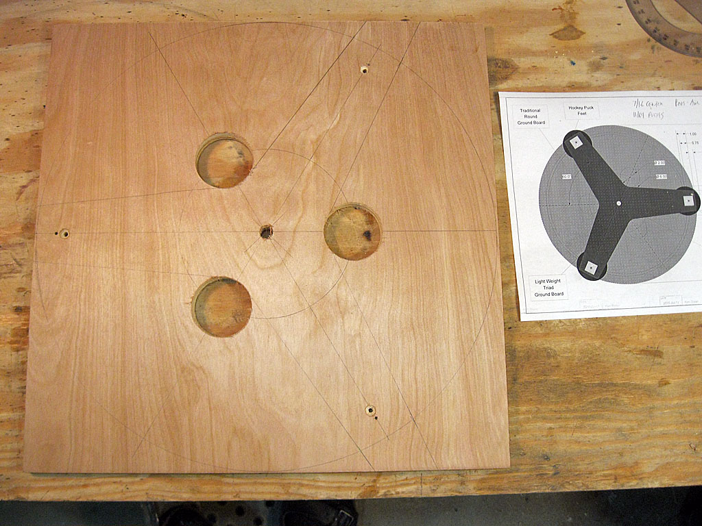
We start by drilling holes. First up is the center pivot hole, which must be drilled out to fit our 3/8 inch threaded Tee-nut. Ours had a 7/16 outside diameter, and we drilled the center hole to this size.
Next, we use an awl to poke starter holes for the pads - these are the marks ¾ of an inch in from the edge. Then we drill out an countersink the three holes for the feet - we are using #8 × 1¼ inch flat head screws, so the clearance hole diameter is 11/64 followed by a countersink deep enough to keep the head below the surface, so it does not interfere with the nearby bearing pad.
If you are making the triad version of the ground board, you should now use a hole saw to drill out the three inner corners of the legs - we designed for a a 2 inch diameter hole, but you can adapt to other diameters or not round the corners at all.
Once the drilling is done, we start cutting. If you are making a round ground board, then saw out the circle a little large, and then shape it into a pleasing round. If you are making the triad version, then make the six straight cuts to define the three arms first, then go back and make curved cuts at the end of the legs (or make them straight, if you are tired of curve cuts!).
That's it, sand and finish it, as usual we are using polyurethane, you can use what you wish.
Ground Board Assembly
While you are waiting for the finish on the ground board to dry, there are a couple of things you can to prepare for assembly: prepare the Teflon Pads and the Hockey Puck Feet.
We are using three hockey pucks for feet - mark the center of each puck and drill a 9/64 inch pilot hole into each one, at leas 1-1/8 deep (it's OK to go all the way through if you wish).
We are using 1 inch square, ¼ inch thick Teflon Pads for the Azimuth Bearing (you can use 1/8 inch thick pads, and sizes slightly smaller than larger than ours). mark the center of each pad, and drill a 9/64 clearance hole for the #6 × ¾ flat head screws we will use to attach the pads. Then countersink the hole so that the screw heads are well below the pad surface.
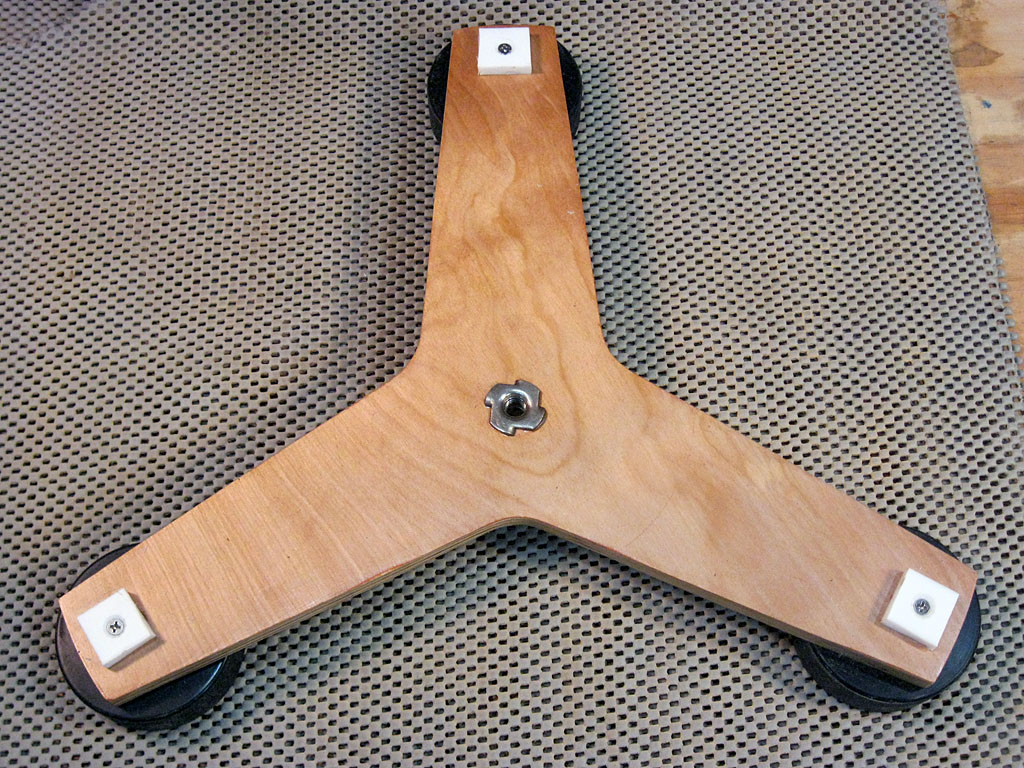
Once the ground board finish has dried, we can proceed with assembly. First, press in a 3/8 inch Tee nut into the center pivot hole from the top - the may require some 'serious persuasion' with a hammer and wood block, as ours had some giant tangs to sink into the plywood.
Then screw in the hockey puck feet with #8 × 1¼ inch flat head screws - the pilot hole in the puck should let you firmly attach them. Finally we use #6 × ¾ inch flat head screws to attach the three Teflon pads. That's it - the ground board is complete.
Final Assembly
All that is left to do is assemble the ground board to the rocker box. For this we will use the following hardware:
- [1] 3/8 × 2 inch Hex Head Bolt (use 2¼ inch for a ¾ inch
thick ground board,
you may need to cut one down from a 2½ inch bolt, a more standard length) - [2] 3/8 inch Fender Washer, 1½ inch diameter (Exact O.D. not critical)
- [1] 3/8 inch Tee Nut (already installed in Ground Board)
- [1] 3/8 inch Hex Nut
Place one washer on the bolt, pass it through the hole in the rocker box, and screw it into the ground board tee nut. Do not tighten, screw it in until about a 1/16 inch gap exists between the bolt head an washer. Then place the second washer on the bolt that is sticking out the bottom of the ground board, spin on the hex nut, and tighten the hex nut to lock the bolt in place while maintaining the 1/16 inch gap below the bolt head. Check to make sure the rocker box rotates smoothly on the ground board, and if it doesn't figure out what is binding and fix it.
Congratulations! You have completed your Dobsonian mount. You might like to add an accessory - an eyepiece rack, which you can find on the next page.
Previous: The Rocker
Box Next: Example Build Plan
Back to the Build a Dobsonian Master
Index