
Altitude Bearings
A Dobsonian Mount is a version of an "Alt-Az" (Altitude-Azimuth) mount. Hence the bearings that allow the telescope to aim in altitude are the altitude bearings. Many people also call these the Side Bearings, as they are located on either side of the tube, attached to the cradle on small Dobsonians or to the mirror box on larger, truss tube Dobsonians.
Sizing the Altitude Bearings
Many small Dobsonians are built with altitude bearings that are too small to work well. This has happened because for many years there was no good information about the need for large diameter bearings, and because many builders looked for objects to make the bearings out of, and what was commonly available, such as plumbing parts, were generally available in small diameters.
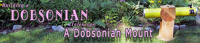
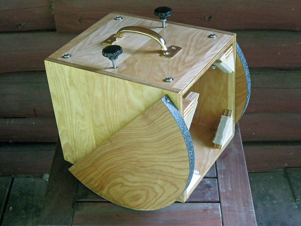
Altitude Bearings attached.
With many thousands of Dobsonians built, much research into the best materials and sizes, and plenty of field experience, it has been learned that a key parameter in obtaining the smooth, jerk-free motion desired in a quality Dobsonian is to have the altitude bearings move a high linear velocity for even small motions. This is achieved by having large diameter bearings: the larger the diameter of the bearing, the longer the linear motion will be over the bearing surface for any given angular movement.
So how large is large? We searched our ATM library and the internet for recommendations, and the only one we came up with that was related to tube diameter or mirror size was from The Dobsonian Telescope by David Kriege and Richard Berry (both were key contributors to the Dobsonian evolution in the 1980's and 1990's). They recommend an altitude bearing diameter of 1.8 × Tube Outside Diameter. Another metric that came up a few times from various sources was at least as big as the primary mirror.
You may notice that many commercial small Dobs use smaller bearings than those that recommended above. Note that many of these use additional components such as springs or clamps to provide more load on the bearings. This can work, but it may need adjusting depending on the altitude angle, and it makes it more difficult to quickly remove the tube/cradle from the rocker box, which can make the scope less portable.
Based on our experience, we would recommend altitude bearing diameters of 1.2 to 1.8 time the tube outside diameter, with a bias towards the large size. The exact size is not critical. for our 8.25 inch tube, we will choose a 14 inch diameter bearing (which is approximately 1.7 × tube diameter)
Bearing Materials
Please read our reference section Dobsonian Bearing Materials to learn about bearing material selection, alternatives and where to obtain these materials. This information was centralized because the same materials are used on the both the altitude and azimuth bearings.
Cutting the Bearings
We build the altitude bearings out of ¾ inch plywood. We will make a 14 inch round disk, then cut it an half to obtain the two bearings. Making a very round circle with perpendicular edges is important for smooth, accurate and wobble-free telescope operation. You will need to take you time with this task, especially if you are using hand tools, to do a good job. This is the most important part of the mount in terms of accuracy to make - while the final diameter of the bearing is not at all critical, the roundness and squareness of the edge are. With power tools, the task is a bit easier, especially if you have access to a router. The router can be fitted to a radius arm, and rotated about the rough-cut circle to produce an accurate edge. But while a router is convenient and quick, you can certainly make the bearings in a few hours with hand tools and careful work.
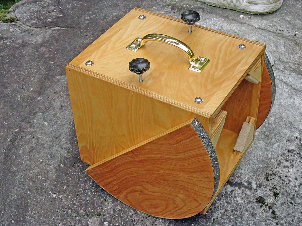
Start by marking the center of the circle with a pair of perpendicular lines at least bearing radius plus 1/8 inch in from the edges of the plywood - you will need these marks when mounting the bearings. Then draw a circle of the appropriate diameter with a compass. You will likely need a beam style compass, most regular compasses don't handle radii larger than 3 inches.
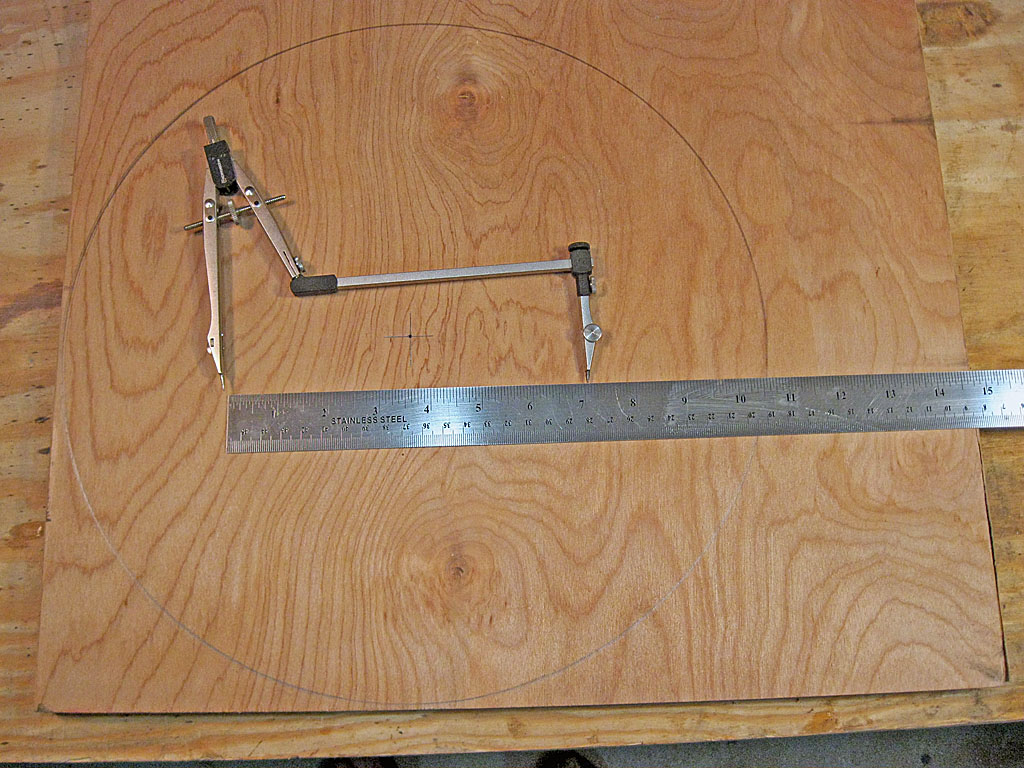
Next, rough cut the circle out of the plywood about 1/16 inch beyond the pencil line (i.e. always have a small gap between the saw the pencil line). Work extra hard to keep the saw perpendicular to the surface so you get a vertical edge. At this point, making a perpendicular edge is more important than making a smooth circle - even with power tools, you will likely get a 'wavy' circle, and this is OK. You want to leave some material to file off, but obviously the less you have to remove to smooth the circle, the faster the work will go. See our reference section on Sawing, Shaping, Drilling & Sanding for more information on tools and techniques.
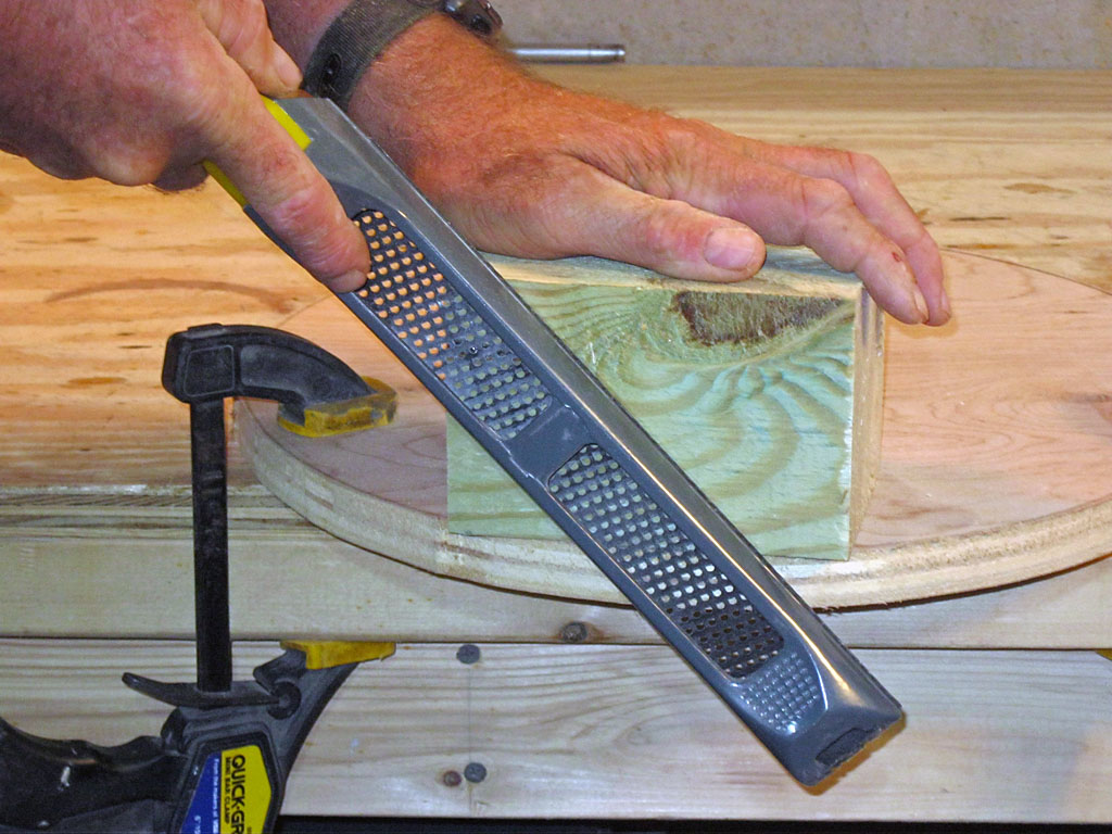
Next we use our Surform tool with a flat blade to shape the edge smooth, round and perpendicular up to the edge of the pencil line. It can be a challenge to keep the edge square. As shown in the photo, using a block of wood can help to keep the tool square to the surface, and produce a good result. See the above mentioned reference section for information on the Surform wood shaping tool.
Finally, we need to sand the edge smooth (the Surform can leave a some 'fuzz' on the edge. This can be done by hand, using the wood block again to keep the sanding block perpendicular.
In this project, we assume the only power tool you have is an electric drill. You can make a sanding jig using your drill that if done carefully can also enhance the roundness of your bearings.
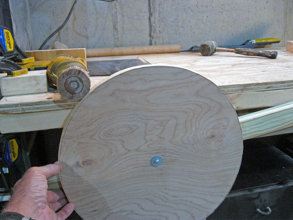
You will need a drum sanding attachment for your drill (Note that the photo shows a flap sander, we were temporarily out of sanding drums for our two inch drum sander, which is about the same size but has a firm rubber drum that will work better). Design your jig for safety - note that our layout prevents the work piece from being pulled into the drill, and if we let go the work falls away from the drill. We mounted our drill to our bench, screwing scrap wood blocks into the bench to position and level the drill, along with some clamps. Then we drilled out the center of our bearing, screwed it into a wood arm, and made a pivot at the far end with a wood screw into the bench. Now with the drill locked on, we can raise the arm until the bearing contacts the sanding disk. Use light pressure to prevent the disk turning at high speed, let is rotate slowly with steady pressure and you should get a nice smooth edge that is also very round.
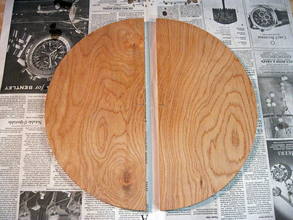
Once the bearing disk is smooth and round, mark a diagonal across the disk for cutting them in half. Also be sure to mark the center with a short line perpendicular to the cut line - you will need this mark to position the bearings on the cradle later.
Cut the bearings in half right down the middle of the line - with equal saw kerf on either side of it. Then sand the cut edge, stand back and appreciate the fine altitude bearings you have made.
Applying Laminate & Finishing
The next step is to apply Ebony Star laminate to the bearing surfaces - Ebony Star is the preferred laminate to use, see our section on Dobsonian Bearing Materials for discussion, how to cut it, and sources. You will need two strips, ¾ of an inch wide (or slightly larger) and just a bit longer than the curved surface of your bearings.
Brush a coat of contact cement on both the bearing surfaces and the back of the laminate strips and let it dry. The plywood will likely need a second coat, as it is pourous. Then carefully align the laminate strips and press them onto the bearing edges. Be careful! Once the contact cement surfaces touch, they will stick, so be sure you are lined up before making contact.
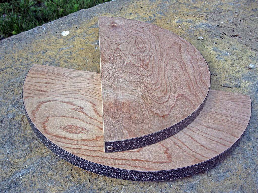
You now need to file or sand the laminate edges flush with the plywood on all sides. Be sure to only stroke towards the wood, if you back stroke you could pull the laminate off. A slight bevel on the edge works well. In our experience, the ends of the altitude bearings are likely to pull off after a bit or normal use, so we like to use a small screw on each end for extra strength - this is optional, and not often done. The photo shows a #6 × ½ inch pan head stainless steel screw securing each end, clearance hole of 1/8 inch drilled in the laminate and pilot hole of 1/16 inch drilled in the plywood. We also clamped the plywood before screwing in the screw to present splitting.
Sand the exposed surfaces, and finish all exposed wood to your taste. We unscrewed one screw on each bearing just a bit, tied some string on it, and used it to hang the bearing so we could finish all sides at once.
Installing the Altitude Bearings
It is really important that the altitude bearings be well aligned on the cradle, so that your telescope will not wobble. The bearings will be screwed, not glued onto the cradle in case we might need to make a small adjustment afterwards.
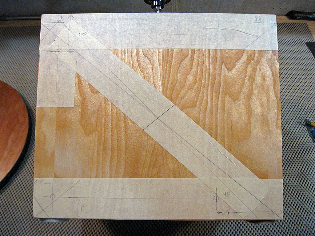
Since our cradle is finished, we use masking tape to draw on. If you have a simple box cradle, draw line from opposite corners to find the center; if you have built our adjustable box cradle, measure ½ inch down from the top corners (to eliminate the extra top gap in this design) and draw your line from there. Where the lines cross is the center of the cradle on the tube. Through this center point, draw a 45° line (use the bottom edge of the cradle as the 0° reference) - this is the top edge of the bearing.
Now lay the bearing on the 45° line, with the center of the bearing on the center mark. Trace the curved edge of the bearing onto the cradle in places where the cradle sticks out beyond the bearing - this will help you locate appropriate places for screws, and help you keep the bearing aligned when attaching it.
Since our bearing is ¾ inch thick and the cradle is ½ inch thick, we will mount the bearing by screwing through the cradle from the inside, to get a ½ inch 'bite' into the ¾ inch bearing with the #6 × 1 inch wood screws we are using. It will also look nicer not to have any screw heads visible on the bearings. You can certainly surface screw through the bearing from the outside if you wish. We located 3 screw holes near the edges of the bearing and the corners of the cradle as shown in the photo - adjust to your dimension in approximately the same relative locations. Be sure to avoid the corner triangles. We also had to notch the pressure beams to avoid hitting the upper screw heads. Make notes so you can repeat hole locations on the other side (we will use out photo to do this, which is why we marked the insets on the tape). Drill 1/8 inch clearance holes in the cradle, remove all but the diagonal masking tape, carefully align and center the bearing, clamp it to the cradle, and screw the bearing in. Now remove the clamps, loosen the screws, remove the last piece of tape, and tighten the screws.
Repeat for the other bearing (make sure they both face the same way!). Now your cradle and is really done with bearings attached!
Next we will built the rocker box, but in order to size it properly, we must find the Balance Point of the Cradle and Tube.
Previous: Build an
Adjustable Cradle Next:
Finding the Balance Point
Back to the
Build a Dobsonian Master Index