
The Rocker Box
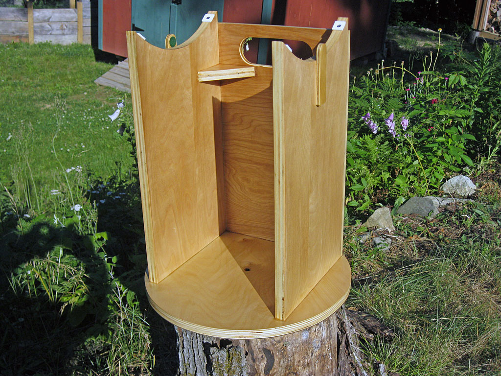
The Rocker Box is a major structural component of a Dobsonian Mount. On the top side, it supports the Teflon pads for the Altitude Bearings, and on its bottom side, it has laminate and a pivot bolt hole for the Azimuth Bearing. In between, we try to build a light yet rigid box structure to connect it all together. While there are a number of minor parts to the rocker box assembly, the four major parts are two sides, one front and a bottom.
Design & Layout
The sides and front are shown in the diagram at right, you might want to study them for a moment before continuing on.
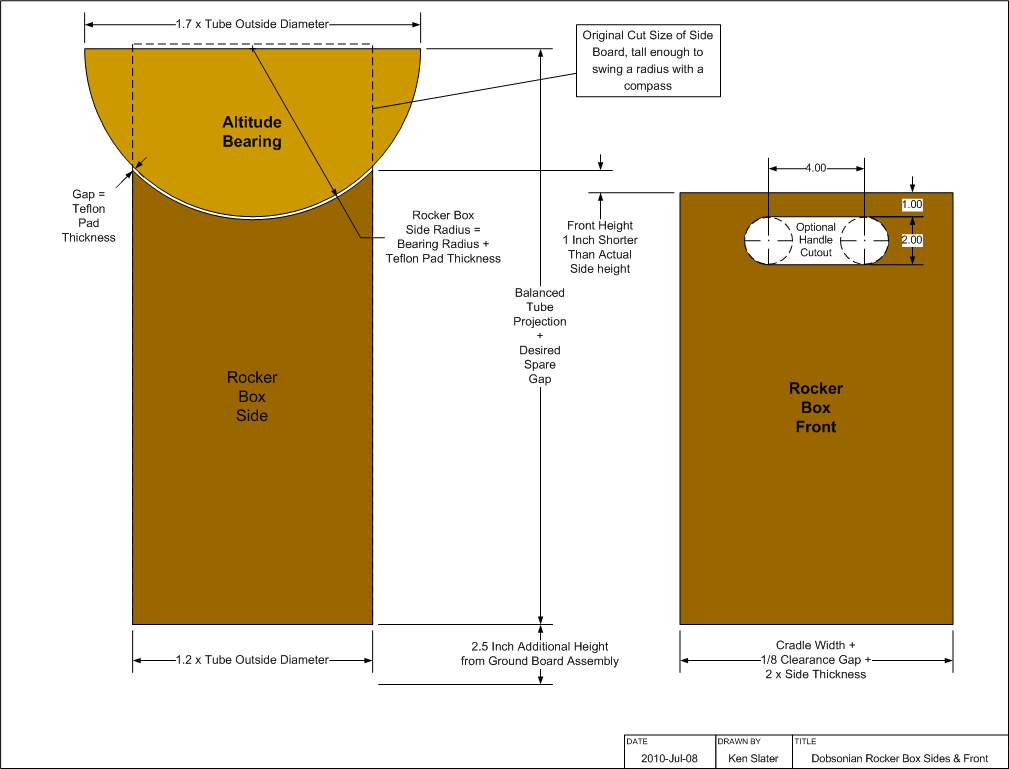
We start by laying out the two sides, which we will make out of ¾ plywood for added stiffness. The width should be approximately the width of the tube cradle (9¾ inches in our case) or approximately 1.2 × the Tube Outside Diameter (9.9 inches in our case). Since this is not a critical dimension, we just rounded up at 10 inches even.
On the previous page we measured the projection of the balanced tube from the center of rotation of the altitude bearings (for us, 21¼ inches). To this we need to add a bit of margin, both to insure clearance of the tube to the bottom of the rocker box, and to allow for additional tube extension should we need balance a heavier eyepiece in the future. You might also want to add a bit to put the scope at a more convenient viewing height; don't go wild here, if you want to add a lot of height it would be better to build a separate, stiff box to set the scope on rather than to make a tall rocker box which could be hard to keep stiff, and with the azimuth bearing at the end of a long rocker box 'lever' make the scope less stable during rotation. We would make the margin no less than 2 inches and no more than 8 inches. We will choose to make ours 2¾ inches bringing our rotational height to an 'even' 24 inches.

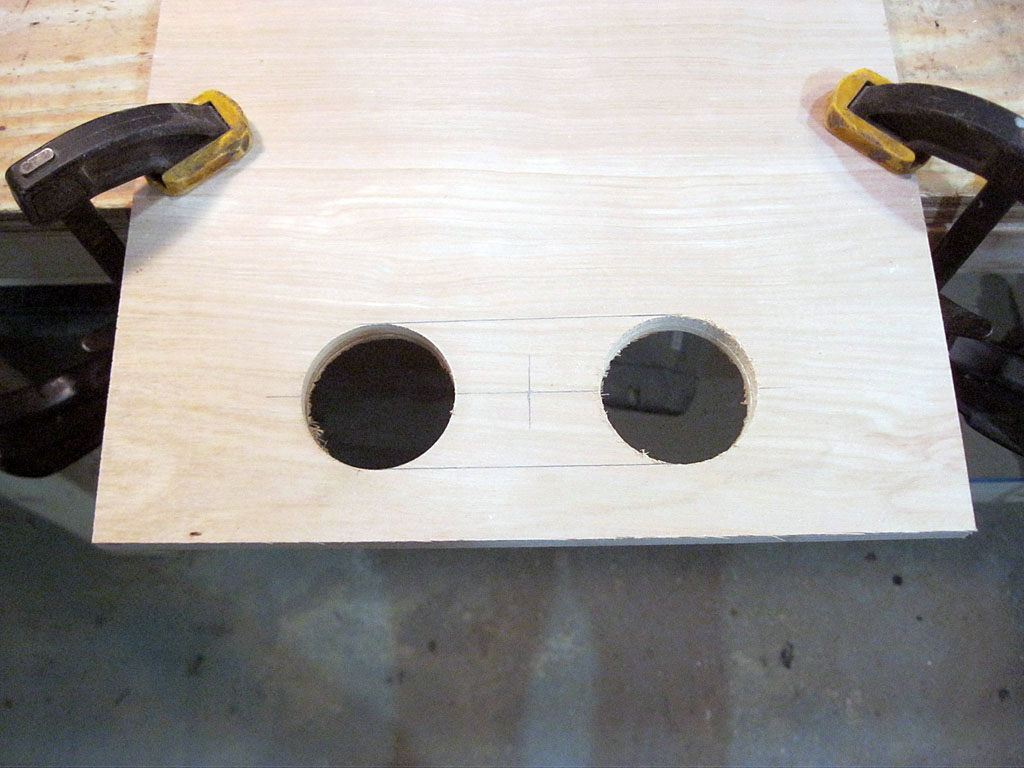
The other two numbers you need to layout the sides are the Altitude Bearing radius (known, but add 1/16 inch for laminate thickness which is now attached) and the thickness of the Teflon pads you will use. We are using ¾ inch square by 1/8 inch thick pads. Pad size is not critical, you want a ¾ inch width to fit on top of the side board, the length could be anywhere from ¾ to 1½ inches. Thicknesses of 1/8 to ¼ inch are fine. See Dobsonian Bearing Materials for information on obtaining Teflon pads.
The front is mainly used to stiffen the sides, we will use ½ inch plywood although you could certainly use ¾ if you wish. The width is critical and needs to be cut with care so your cradle can swing freely:
Rocker Box Front Width = Cradle Width + 1/8 inch Clearance Gap + ( 2 × Side Thickness )
As shown in the diagram, the front height needs to be about an inch less then the laid out maximum height of the rocker box, to give the cradle plenty of room to swing. We also show an optional handle cutout in the front, which will make the rocker box and ground board assembly easier to carry.
The Rocker Box Bottom is a circle of ¾ inch plywood. It must be sized to fit the entire rocker box within it. Calculate the diagonal length of the rocker box bottom ( = squareroot[ width2 + length2 ] ) remembering to add on the thickness of the front panel to the length of the sides. We get approximately 15½ inches for our rocker box, so we will make the bottom 16 inches in diameter, as you should add one half to one inch to be safe and account for the fact the rocker box in a rectangle and not a square.
Make a good mark in the center of the circle (we poked it with an awl), you will need it to drill out the hole for the pivot bold later. Also, you should draw two straight line at right angles through the center point, we will use these to align the top and sides to the bottom. Before you cut the bottom, you might want to lay it out, and place the rocker box sides and front on it to make sure it fits.
As an aide to rocker box assembly and gluing, we will cut a scrap board to a length of exactly Cradle Width plus 1/8 inch. This can be clamped inside the open back end of the rocker box to help keep it square while the glue dries. Only the length dimension is important, use whatever size scrap you have handy.
There are a few other small parts we will need; we will layout and cut them when we need them. Now, let us assemble the rocker box and test it.
Cutting & Assembly
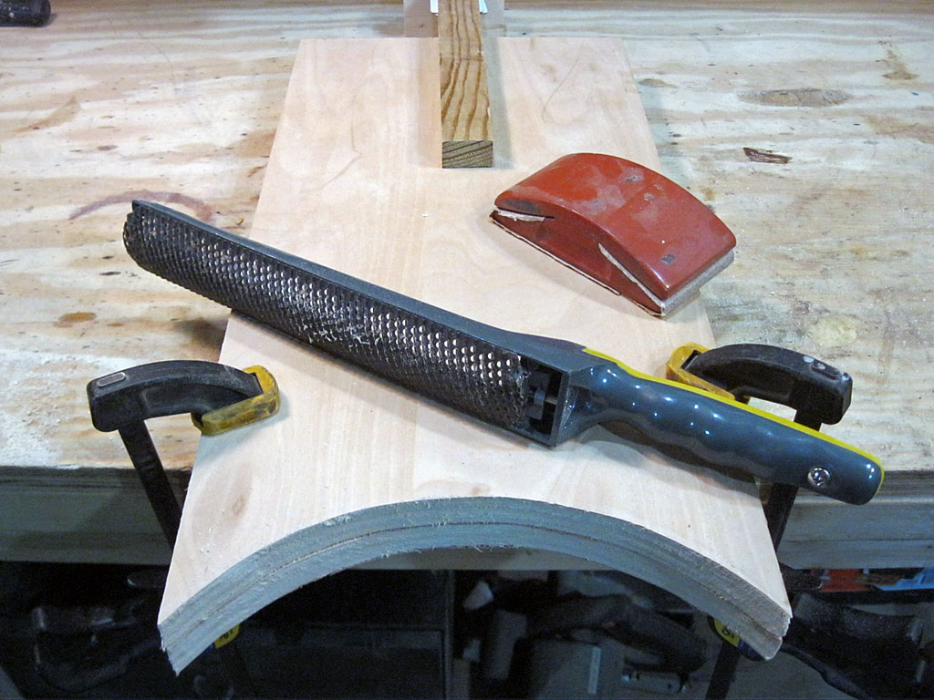
With the information from the above section, cutting out the parts should be very straightforward. I know curved cuts are time consuming with hand tools, but the good news is that the level of precession for need for both the rocker box tops and the rocker box bottom are not critical, unlike the Altitude Bearings themselves. What is important is the the two sides of the rocker box be identical, so you might want to clamp them together and shape the curves while ganged. The critical parts are the rocker box curve ends, where the pads will sit - make sure they are the same on both pieces (mark the front of each piece so you will not reverse one when assembling). Also, round over the pointy rocker box curve ends with sandpaper to about a 1/8 inch flat between the curve and side.
The front is a simple rectangle made from ½ plywood. If you are making the optional handle, you can use a 2 inch hole saw to make the round ends, or cut the curves with a coping or jig saw, which you would use in any case to cut our the straight parts between the holes. Using the SurForm and sandpaper, round over the handle opening edges for a comfortable grip.
The circular rocker box bottom curve is purely aesthetic - smoothness counts for good looks, absolute roundness is not critical. If you really hate making curves, you could inscribe an octagon on the outside of the required circle and use straight cuts (perhaps rounding the pointy vertices with your SurForm tool a bit).
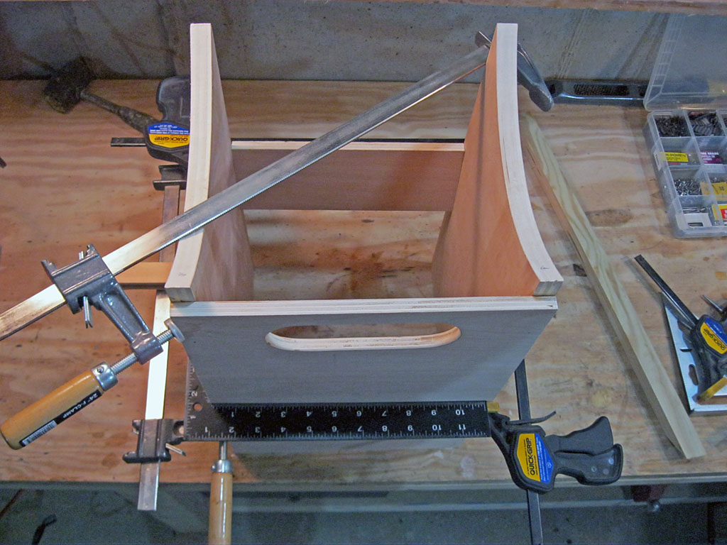
Our first task is to assemble the front to the two sides, nailing and gluing them in the same way we did the cradle. It is important that the rock box be square in all dimensions, so have a flat surface to sit it on. If you sit the sides on their back edges, and clamp the scrap pieces mentioned above between them, you should have an easy time spreading glue on their front edges and nailing the front to them. Then turn the assembly to it's normal position, check for square between front and sides and be sure all pieces sit flat on your work surface. Let it dry.
Once the rocker box glue has set, you should test the cradle in tube in it to make sure you do not have any problems. You should be able to sit the sub vertically in the rocker box, placing the altitude bearings on the rocker box sides, and observe the 1/8 inch clearance between the cradle and rocker box. Also, make sure you have the the expected tube bottom gap.
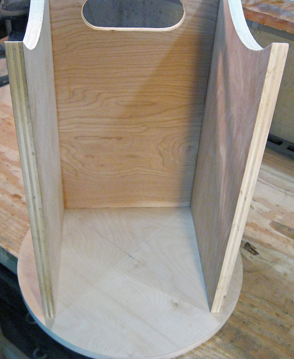
Next check the that the rocker box fits on the rocker box bottom circle which you should have laid out but not cut. Once you are certain the size is right, cut out the rocker box bottom circle. Now, carefully line up the rocker box inside corner edges on the two right angle line you drew; this centers the rocker box sides on the rocker box bottom. Note that the rocker box front projects beyond the sides, and it will look from the outside like the rocker box is not centered as the front will be closer to the edge then the back of the sides - this is expected.
Trace the two rocker box sides onto the bottom with a pencil. Then remove the box, and mark the location of 4 holes centered on the edges and approximately 1¼ inches in from each end. Drill with out with a 1/8 inch drill bit. Flip the bottom over and countersink each hole (we need to make the screw heads sit below the bottom surface for when we cover it with laminate). Now comes the tricky part, we need to screw and glue the rocker box to the bottom. We will use approximately 1½ inch wood screws or drywall screws (we had some 1-5/8 drywall screws handy and used those). Place the rocker box on a workbench or table where you can hang part of it over the edge. Place the rocker box upside down on the floor, spread glue on the 3 bottom edges, then pick it up and place in back on the marks on the bottom. Now slide the bottom partly off the workbench so one hole is exposed, and screw in one screw without dislocating the parts. Work you way around to all four screws, hanging one hole off the workbench at a time. Then clean up any glue that has seeped out with a damp rag, and set the assembly aside to dry.
Now is a good time to sand everything and remove any pencil marks, before we put on some smaller parts that will make this more difficult. Be sure you know where the center of the bottom is; poke it with an awl or drill a 1/8 hole there so as not to lose the location.
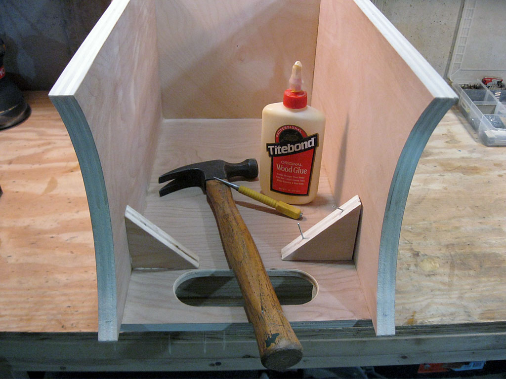
While the bottom part of the rocker box is pretty rigid, the upper, open part is less so. To improve its rigidity, we will add a couple of triangular corner braces just below the handle opening. These need to be sized for your mount so they do not interfere with the cradle or tube. We cut a 3 inch square of ¾ inch plywood in half, tested clearance with the tube set in the mount, and then glued them into place, holding them with a couple of finishing nails.
Completing the Altitude Bearings
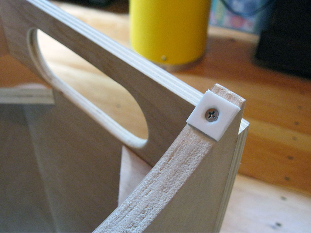
Now we will complete the Altitude Bearings, working on the Rocker Box parts of them. We need to install four Teflon Pads, one near each end of the curved rocker box sides, for the semicircular bearings attached to the cradle to ride on. See Dobsonian Bearing Materials for information on obtaining Teflon pads. We will use ¾ inch square, 1/8 thick pads which we cut by scoring with a utility knife from a small Teflon sheet we had on hand. The ones you use should be no wider than your side boards are thick, no longer than about an 1, and any thickness over 1/8 will be fine. We then drilled a 9/64 inch hole in the center and countersunk it for a #6 stainless steel flat head screw that is ½ inches long. Be sure to countersink deep enough so the screw head is below the surface - you don't want to scratch your laminate bearing surface with a screw head that is too high. Install as shown in the photo, a little ways from each end - hole the pad where it should go, poke a starting hole with an awl through the center, and stall with the screw. Now place your tube/cradle assembly on the rocker box and check for wobble free, smooth operation. If your scope wobbles, you may need to shim or lower a pad, or adjust a bearing on the cradle. Our only problem was our rear pads were installed a little too close to the end, and we could not get the scope 100% vertical - moving them in a little bit allowed for this.
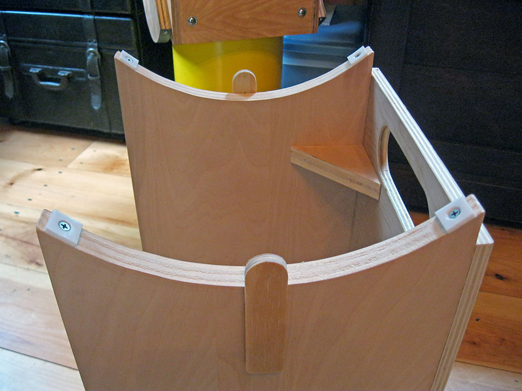
You may notice the cradle wants to slide from side to side a bit, an sometime the cradle will collide with the rock box. To solve this problem, we need to make and install bearing retainers, which will have a thin felt pad on them that rests against the outside of the altitude bearings and prevents side-to-side movement. Many Dobsonians use 'full length' bearing retainers, that run from the rocker box bottom up the middle of side boards and end about an inch above (where the felt pad is) - this also stiffens the side board. We are going to be more minimalist, and use a 4 inch by 1 inch piece of plywood. Use the thinnest plywood you have on hand, we have some ¼ inch handy and will use that; thicker is fine, it just doesn't look quite as nice. Cut out the retainers, round the ends if you wish, and file, sand or whittle the top inch down by an amount equal to your thin felt pad thickness. The goal of all this is not to press on the bearings with the felt, but to provide a soft cushion to prevent them from sliding side-to-side. Glue the retainers to the rocker box sides in the center, projecting up about an inch. After finishing the rocker box with paint or sealer, install thin felt pads on the inside of each one.
Beginning the Azimuth Bearing
The azimuth bearing is formed between the Rocker Box Bottom and the Ground Board Teflon Pads, rotating on a Pivot Bolt the connects these two parts. We will now construct the rocker box portion of this bearing.
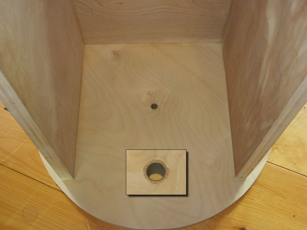
We will use a 3/8 inch diameter bolt for the pivot. You might want to put a bushing in the rocker box bottom pivot hole to prevent wear over time. We went looking for a 3/8 I.D., 1/2 O.D., ¾ inch long plastic spacer in the small parts drawers of our local hardware store. We didn't find them, but did find a 3/8 I.D., 1/2 O.D., 1 inch long bronze bushing. We purchased that and cut it down to ¾ inches long. You need to drill a hole of the appropriate size for what you plan to use - 3/8 inch if you are going to just use a bolt, bigger for a bushing. Make it as vertical as possible so the telescope will rotate smoothly. We had a 31/64 inch drill, 1/64th small than our ½ bushing, and used that, making the bushing a 'press fit' when coaxed into position with a wooden block and hammer. If your bushing slides out of the hole, try a little tape around the outside or some glue to hold it in place for now and to prevent any wobble. Once we install the laminate, it won't slip down, and in use there is no vertical pressure on it.

The final step in constructing the azimuth Bearing is to cover the bottom of the rocker box with Ebony Star Laminate. Only the outer 2 inches need to be laminated, but for small dobs it is more work to cut a ring so we just laminate the entire bottom. Use the same procedures we used for the Altitude Bearing laminate - cut the laminate a little bigger than the surface to be covered (we cut our sheet into an octagon 1/8 inch larger then the rocker box bottom on all sides), coat each part with contact cement (2 coats), and when dry press together. It is often helpful to place some thin dowels or sticks between the laminate and rocker box to prevent the two parts from touching while you align them - then slip out the dowels to make contact and get adhesion. Trim (file and sand) the edges flush. Once that is done, put a scrap block of wood under the center hole and drill out the 3/8 inch hole for the pivot bolt to pass through.
Seal It Up
The only thing left to do is a final sanding and the painting or sealing. The only item that needs to be removed for this are the Teflon pads, and they unscrew quickly. We will, once again, polyurethane ours, you can paint or use alternative sealers of your choice. When the sealing is complete and dry, you need to reinstall the Teflon pads and add a couple of thin felt pads to the bearing retainers.
The rocker box is complete (photo at top of page shows completed rocker box with thin felt pads installed on the bearing retainers). Now we have one part left to construct, the ground board, which is very simple and quick to build compared to the other parts.
Previous: Finding the
Balance Point Next: Ground
Board
Back to the Build a Dobsonian Master
Index