|
||||
Reading ShadowgramsWhat is a Shadowgram?
At Stellafane, a Shadowgram is also the talk given at convention before the keynote speaker. Traditionally
it was used to pace the program during twilight, until it became dark enough for the keynote speaker to
be able to use projected images. 'Scotty' Houston (1912-1993)is the most famous and beloved Shadowgram speaker.
A Shadowgram is the image you see in a knife-edge, or Foucault, tester. It is a representation of the surface profile of the mirror under test. However, it is not a direct representation, and you must 'read' the shadowgram to translate it to a physical mirror surface profile. Once you have this information, you can make a figuring plan for which areas to work on to improve your mirror's figure. Note that this page is going to deal with qualitative results from the shadowgram; we also take zonal measurements and use data reduction software to get quantitative results. The qualitative results are most useful when figuring to a sphere, or when you have noticeable zonal defects you need to correct, and you can usually get enough information from these qualitative results to correct the these problems. The quantitative measurements are usually not used until the qualitative results indicate your mirror has a parabolic shape with no major defects. What does a Shadowgram Look Like?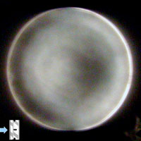 Shadowgram of a Parabola The photo at right is typical shadowgram taken in white light at the Stellafane Mirror Class in 2008. As you will learn below, the shadows are indicating the shape of the surface, and if you imagine that the mirror is illuminated from the the right side (it isn't, in fact) you can imagine that the surface gently slopes up to a crest at about 70% of radius and then slopes down again to a central low spot. This shape is often called the 'donut' as it looks to many (hungry?) mirror makers like a donut or inner tube. This is your goal: this shape is characteristic of the parabola. However, hyperbolas and ellipsoids also look like this; you must take quantitative measurements to tell them apart. To begin figuring, you don't need to do this; rather you need to work on surface quality and getting first to a sphere and then the parabolic shape. Note the much smoother appearance of the surface compared to the shadowgram at below right. Reading Surface Quality from a Shadowgram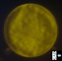 Dog Biscuit Surface with a raised edge ring. Photo courtesy of Dave Tabor The photo at right is a shadowgram taken in yellow light and shows a mirror that has several problems to be fixed. Most noticeable is the overall mottled or blotchy appearance, which is indicates that the optical surface is not smooth, and in fact will scatter a lot of light instead of focusing it. Shadowgrams will reveal many surface defects that are seen as small shadows on the shadowgram: pits, scratches and various surface defects with fanciful names like Dog Biscuit, Orange Peel and (more down to earth) micro-ripple. While a few pits or scratches can be tolerated, overall surface quality needs to be smoothed out. As you will learn below, the large scale shadows on this mirror indicate there is a raised ring around the edge. The little razor blade icon in the lower right will be explained below, and is there to help you read this shadowgram.
The following is an excerpt from the talk A Introduction to Foucault Testing and Foucault Testers
given at the 2002 Stellafane Convention by Ken Slater of the Springfield Telescope Makers.
Reading ShadowgramsIn this example, we will use 'cartoon' figures to illustrate the process and teach you how to do this yourself. In looking at an actual shadowgram, there are not sharp edges to the shadows and the image is jiggling around in the tester. In order to eliminate this potential source of confusion, we have used these 'ideal' cartoon figures. It should not be hard to apply what you learn to the real world; but you will need to develop skill in deciding which zones are dark, light and nulled in the actual shadowgram. Knife Edge Direction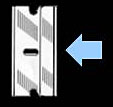 Knife cutting from the right. Before we begin, there is one important piece of information you must know: What side is the knife cutting in from? Testers can be built to have the knife cut in from the left or the right (this is from the operator's perspective, sitting behind the tester). There is no standard, so you must look at your tester and remember the knife edge direction. When looking at photographs or illustrations of shadowgrams, you don't have the tester to examine, therefore you need an indication of which side the knife is cutting in from. We use the symbols at right to indicate, either a single-edged razor blade or a light blue arrow, or both, to indicate the direction of knife travel. In this case, the knife is cutting in from the right. This is important, if you get it backwards, what you interpret as a raised area will actually be a low spot, and vice-versa. The figuring plan you come up with will only make the situation worse, not better. The Sample Shadowgram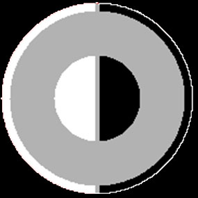 Sample Shadowgram Our sample shadowgram is shown at right on a black background. There are three concentric zones on this mirror: A center zone which is light on the left and dark on the right; A middle zone which is shown as gray and is intended to indicate a nulled zone; and finally a thin edge zone which is also light on the left and dark on the right. Diffraction RingAs in a good actual mirror, there is also a very thin, bright ring all the way around our sample shadowgram, most apparent on the right edge because it is contrasted against the dark zone; it is most visible as the knife edge is just about to cut off all light. Any light passing a physical edge is diffracted; the sharper the edge the brighter the ring. The diffraction ring is the tester source light being diffracted by the edge of your mirror. Lack of a visible, uniform (completely encircling) diffraction ring is usually a sign of a turned up or turned down edge. So while it is ignored in reading Shadowgrams, it's absence is a warning that you need to be concerned about the shape of your edge. The Null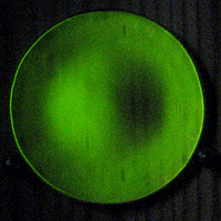 Actual Shadowgram
Similar to our example, the edge zone is thinner, and the central hill is wider. Twice now we have mentioned a nulled zone - what is it we are talking about? In mirror testing, a Null is a visual indication that we have positioned the knife edge exactly at the radius of curvature of that zone, and as we cut the knife edge in, we se no motion from the left or the right of shadows in that zone, but rather the zone grays and then blacks out uniformly, all at once, as the knife edge cuts in. In practice, you can carefully adjust the knife edge on your tester just to the point where the shadows begin to gray out the zone, and that zone will shimmer as you watch due to small vibrational movements in your tester. You can also see surface defects very well at this null point. Foucault, or Knife-Edge testers are null testers - they allow you to find the the exact radius of curvature of a spherical mirror, or smaller spherical zones of more complex mirror shapes like parabolas. Once we locate the null of a zone on the mirror, the shadows patterns of the other zones give us surface profile information, which we teach you to extract in the next few simple steps. A Horizontal Strip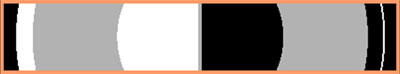 The Horizontal Diameter of our Sample Shadowgram The knife-edge test really only tests a single horizontal diameter of a mirror. Many people rotate their mirror by 45° and 90° to test other diameters and detect any astigmatic (axially non-symmetric) problems. In any case, the next step in reading a shadowgram is to focus on the zones across the horizontal diameter of the mirror. Use a Magic Light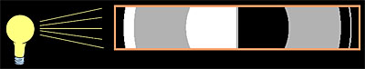 The Magic Light comes from opposite the knife edge. We know the mirror is illuminated from the front by the tester, but in order to interpret the shadowgram, we imagine the mirror is illuminated from the side opposite the knife edge by an imaginary magic light. Now, looking at the horizontal strip, label the bright zones as "Up", the gray or null zones as "Flat", and the dark zones as "Down":  The Labeled Horizontal Strip The imaginary light is 'Magic' because it has the unnatural ability to illuminate zones even if they would normally in the shadows of other zones; magically, our light penetrates these blockages and brightens every upslope. Thinking about a mirror other than our example, lets us imagine a mirror with a raised ring around the edge and a central depression. We would see a shadowgram that we would label as Up-Down-Flat-Down-Up-Flat-Up-Down. If our light was not magic, the Up of the central depression would not be bright, its illumination would be blocked by both the raised edged ring and the flat zone to its left. But our imaginary 'magic' sidelight does not let these physical facts get in the way, and the upslope of the central depression will be a bright zone anyway. Build a Rough Profile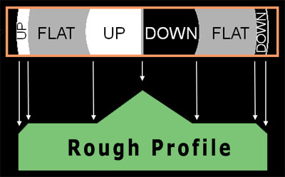 Building a Rough Profile from the Labeled Horizontal Strip Translating the Labeled Horizontal Strip to a Rough Profile, we draw up and down slopes at 45° angles, and flat regions are, well, flat. The horizontal size of the regions map exactly to the physical mirror, and are directly readable from the shadowgram. The heights and slopes of the regions will be adjusted in the next step. The Rough Profile for our example is shown in green at right. This is a first approximation to the mirror shape, what we call the 'flatland' shape. But we know that the 'flatland' flat zones are really spherical nulls, so we next make a second transformation to the real physical profile of your mirror. With practice, you will be able go directly to this final physical profile. The Actual Mirror Shape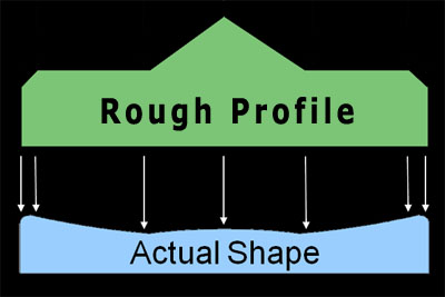 Transforming the Rough Profile to the Actual Mirror Shape The final step is to transform the Rough Profile to the Actual Mirror Shape. We use our knowledge of what the actual mirror must look like in order to do this, and take horizontal zone sizes from the Rough Profile, while scaling the vertical dimensions based on our mirror and testing knowledge. We suggest you always start with null zones to draw your Actual Mirror Shape profile. The null zones are drawn as flat horizontal plateaus in the Rough Profile, but we know they must be have a spherical shape to null on our tester. So we start by drawing a spherical baseline for our mirror profile. Note that in the illustration at right, the actual profile vertical dimensions are greatly exaggerated; for a 6-inch f/8 mirror the maximum vertical change in height is 0.047-inches. Now we turn our attention to the central zone, and see in the Rough Profile it is higher than the 'null plateau'. This is known as a central hill, and it reality it is a zone that is focusing longer than the null. That means its slope is shallower than the null zone, so it is in fact higher, an area where glass needs to be removed. We draw this as a shallow bump in the exaggerated Actual Shape drawing, but it probably does not bump up like that at all, instead of following the curve of the null zone it is probably just a bit less curved (flatter). In any case, it is an area that glass needs to be removed, so the blue Actual Shape drawing above will not lead you astray in figuring. Finally we work on the edge zone, and indeed, this mirror has the dreaded Turned Down Edge (TDE). We can see this from the Rough Profile. Again, in terms of Actual Shape, the null zone should curve up smoothly all the way to the edge. Our shadowgram has told us it does not, instead the edge flattens out, focuses long, and will not null at this position of the knife edge. On the Actual Shape drawing, we round over the edges to indicate this. TDE is dreaded because the only cure is to lower the curve of the rest of the mirror below it, and this takes a lot of time because there is a lot of glass to remove. You can now Make a PlanWith knowledge of the actual shape of your mirror, you can now make a figuring work plan to correct your mirror to the desired shape. You now know how to read shadowgrams, and you should be able to transform any shadowgram you see into an actual mirror shape, as long as you know which way the knife is cutting in from. ReferencesThe concepts of shadowgram transformation presented here are also shown, with more examples in [Brown96] in the section on Testing and Correcting. [Texereau84] does not present a method of interpreting shadowgrams, but does have table of apparent profiles and describes in text their actual shape. Beyond that, there are not any more books we are aware of that have useful sections on on interpreting shadowgrams for beginners. On the web, an excellent page exists with outstanding illustrations at the ATM Workshop: Understanding Foucault: A Primer for Beginners (This is also currently available as a paperback book). Please see our companion page, Understanding Foucault Testing, to learn how the test works and why the shadows arise using simple geometric ray diagrams. |
||||
|
Back to the ATM Index Page |
||||