|
||||
Understanding Foucault TestingYou do not actually have to understand how Foucault, or knife-edge, testing works in order to use it. It is possible to follow instructions and successfully test your mirror. However, many people find that understanding how the test works helps them work faster and more confidently while testing, for if you understand how it works you can more easily interpret what you are seeing, rather than having to look it up in reference material. In fact, the knife-edge test is very simple in operation, and is not difficult to understand. Here is how it works:
The following is an excerpt from the talk A Introduction to Foucault Testing and Foucault Testers
given at the 2002 Stellafane Convention by Ken Slater of the Springfield Telescope Makers.
Why the Shadows Behave as they Do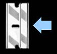 Knife cutting from the right. Using four simple light ray diagrams, this page will explain how the shadows in a shadowgram are created, which really is quite logical and simple. The companion page, Reading Shadowgrams, will help you understand the surface contour of your mirror based on the observed shadows, and also discusses surface quality. As described in Reading Shadowgrams, it is important to know from which side the knife edge is cutting in. For the examples on this page, the knife is always cutting in from the right as indicated by the blue arrow icon. About Radius of Curvature & FocusKnife edge testing is done at or near the Radius of Curvature of your mirror, not its focal length. Please do not be confused by the term 'focus' here, we are using it to indicate where a bundle of light rays converge to a point. This is indeed a focus in optical terms, but it is not at the focal length of your mirror. A parabolic mirror will focus parallel rays of light (light coming from 'infinity', or a very long way away compared to the focal length of the parabola) and bring it to a sharp focus at a single point. The distance between the mirror surface and this point of focus is called the focal length. A sphere will also focus parallel rays at the focal length, but the focus will not be sharp, it will be spread out (this is called spherical aberration). In knife edge testing, we do not use a parallel, 'from infinity' light source, we use what is fundamentally a point source. We need to test at a spot where we can send light out from a point source and have it return to the essentially the same point. For a spherical mirror, this point is at the radius of curvature, which is twice the focal length. A sphere produces a sharp focus under these conditions, while the parabola of the same average RoC produces a spread out focus. We use this spread out focus to our advantage, as the spread out focus produces the informative shadowgrams. About our DiagramsThe four diagrams on this page are highly simplified schematics of a mirror being knife edge tested. The mirror, with a very exaggerated profile, is shown at left in blue. We are looking down on the test setup from above. Light rays reflected from the mirror are shown as colored lines, often yellow but when we need to distinguish individual rays we use other colors. Illuminating rays and the light source are not shown, as they do not vary and would clutter the diagram. The light source would be near the knife edge. Towards the right center, you can see a knife edge cutting the reflected rays from the right, and a symbolic eye is located near where the tester would observe the shadowgram, as close as possible to the knife edge. Below the eye is a depiction of the shadowgram, what the observer would see with this tester configuration. The small blue arrow at extreme lower right reminds us that this shadowgram is made with the knife cutting in from the right. The Sphere at Radius of Curvature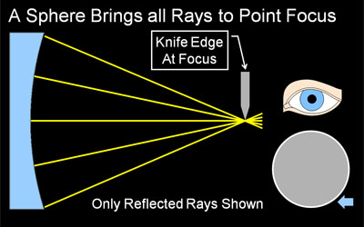 Figure 1: A Sphere produces a Null (even, flat gray) A knife-edge tester is a null tester for a concave spherical surface. In this context, null means there are no shadows observed, when the knife edge cuts into the returned beam, the mirror 'blinks' from light to dark with no observable moving shadows. Why is this? Recall we are testing at the mirror's radius of curvature. Our light source and knife edge are both at the center of a vary large sphere, and the mirror represents a small segment of that sphere. When light floods out from the light source (not shown in our diagrams), it will strike at every location of the mirror exactly perpendicular to the surface, and be reflected exactly back on itself. That is why we test at Radius of curvature. The rays will reflect to a point focus exactly at the radius of curvature. When the knife edge cuts into this reflected beam at the radius of curvature, it will cut off all the light at once, because at focus the returned light cone is a single very small point. Hence we observe the null, a sharp, quick darkening of the mirror with no observed shadows or shadow motion. Contrast that to the knife cutting into the returned light cone away from the focus at radius of curvature in the next section. Knife Edge Inside of Radius of Curvature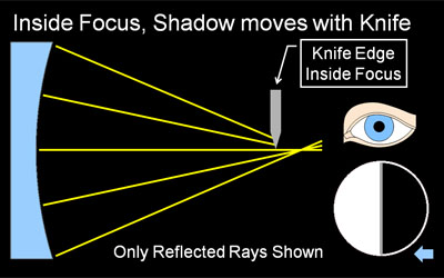 Figure 2: Knife Edge Inside RoC, Shadows move with Knife. If our knife edge is positioned closer to the mirror then the focus at Radius of Curvature, we have the situation depicted in Figure 2. As you can see from the diagram, the knife will not be able to cut all the reflected rays at once, instead it cuts off the rays from the right side of the mirror first, then the center, and finally cuts off the rays reflected from the left side. In this case, we observe a dark shadow moving from right to left across the mirror, traveling in the same direction our knife edge is moving (If our knife edge was cutting in from the left, the shadows would travel left-to-right. This is why it is so important to know which way the knife is moving in your tester). As we get closer to radius of curvature, the shadows will move faster in relation to the knife, as we are cutting more rays with each turn of the knob, because they are spaced closer together. As described above, when we are at Radius of Curvature, we cut all the rays at once, see the null, and therefore observe no shadow motion at all. Knife Edge Outside of Radius of Curvature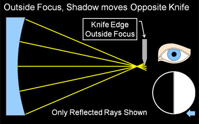 Figure 3: Knife Outside RoC, Shadows move opposite Knife An interesting thing happens when the knife edge is outside of the radius of curvature: the direction of the shadow travel reverses, and the shadows move opposite the direction of the knife. Why does this happen? At the radius of curvature, the reflected rays cross over each other, left to right (they become mirror-reversed). Now, when the knife cuts in from the right, it first cuts the returned ray from the far left side of the mirror. Only when the knife has moved all the way to the left will it cut off the reflected ray from the far right edge of the mirror. We use this fact to easily adjust our tester to find the null, or radius of curvature, of a particular zone on the mirror:
A More Complex Example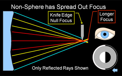 Figure 4: Complex Mirror Shape and Shadogram Up to this point, we have been using a spherical mirror for our examples, because a it has only one zone for the entire mirror and the shadows are simple to see and understand. However, most of your testing will be done with more complex surface shapes, so let us discuss how they work in the knife edge test. In Figure 4 we have made the mirror more complex. Our simple sphere has been replaced with one that has a turned down edge and central hill (both very much exaggerated in the diagram). This mirror has three distinct zones, and the reflected rays from each zone have been colored differently to help you sort them out on the diagram. On a complex mirror each zone will likely have a different radius of curvature, and therefore the reflected rays will focus at different points. We exploit this fact to produce the shadowgrams that give us so much information about the mirror under test. Referring to Figure 4, the knife edge is positioned at the RoC of the middle zone (yellow rays). It has cut into the returned light cone and produced a null for this zone's focused bundled of rays. However, the center zone (red rays) is flatter than the middle zone, and therefore has a longer RoC. Its rays will come to focus beyond those of the middle zone. As the knife edge cuts into the returned rays, it also cuts the central zone rays inside of the central zones RoC, and we see the characteristic shadows moving with the knife edge indicating we are inside the RoC of this zone. Similarly, the edge zone (blue rays) is turned down, or flatter, than the middle zone, and it too focuses longer, so its shadow also moves with the knife edge. The resulting shadowgram is shown in Figure 4 below the cartoon eye. You can learn how to read this shadowgram on our Reading Shadowgram page, although you already know a lot about the RoCs of the three zones just by understanding how knife edge testing works. Note that we could adjust our tester to be at the RoCs of the edge and central zones (which are identical in this example to keep it simple, not a common occurrence). In this case we would observe a null in those zones, and shadow movement would indicate we were outside of RoC for the middle zone, because it has a shorter Roc than the other zones. In doing quantitative testing, we successively null each zone on the mirror, using the shadow movement to guide us to that zone's null. The position of the tester at each null, towards or away from the mirror, measured in thousandths of an inch, is used as the primary input data to a Foucault data reduction program. |
||||
|
Back to the ATM Index Page |
||||