

Building the Mirror Cell

Finally we are ready to build something! The mirror cell should be a fun, relatively short project. Be sure you have read the previous page, The Primary Mirror Cell, as that is where we have listed the material and hardware for this project.
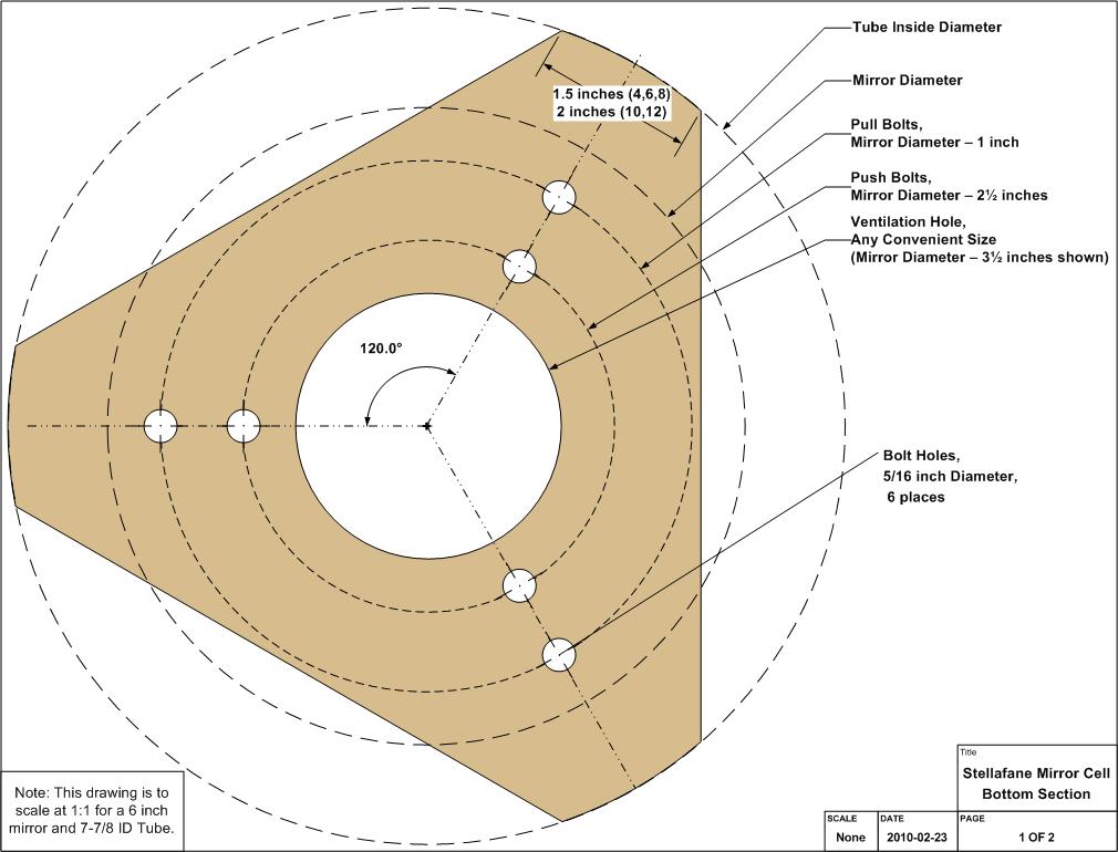
Plans: Ours are drawn so they will scale for any reasonable tube diameter and primary mirror between 4 and 12 inches, so you will find few absolute dimensions on them. Rather, most dimensions are specified as relative to tube and mirror diameters. View the plans online by expanding the thumbnails to the right, or get a PDF version for printing: Cell-Plan.pdf.
Layout
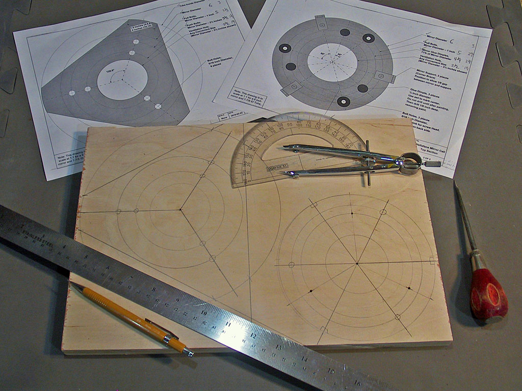
On a suitable piece or pieces of ¾ inch plywood, using a compass, protractor, ruler and pencil, lay out the two parts of the mirror cell, leaving at least 1/8 inch margin of wood around the edges. Before we started, we calculated the various diameters and wrote them in on the printed out plans, then divided by two to get the radii to set our compass. The critical items here are the tube inside diameter (we need a snug but sliding fit) and the pull bolt holes (they need to align between parts so the bolts don't bind).Pay special attention to the radial 60° lines and the two pull bolt circles when you draw them in (draw the two pull bolt circles without changing the compass setting).
We need to know where the push bolt circle is on the back of the mirror cell, so that the mending plates can be attached over them. Once the front of the mirror cell is laid out, drill a 1/16 inch hole through the center point, then flip the piece over and draw the push bolt circle on the back, using the 1/16 inch hole as the center point. We will use the pull bolt holes after they are drilled through to line up the mending plates around the circle we drew.
Cutting out the Parts
Refer to our general section Cutting, Shaping, Drilling & Sanding Plywood if you need more information about the tools and techniques to accomplish this task. Cut the mirror cell top section out just outside the pencil line, then do the final shaping with the wood shaping tool. The final size of this top piece is not critical, you just want to shape it to look good and be smooth. It's a good piece to practice on, we have some more critical fits later. Be sure to keep the shaping tool flat against the edge, don't angle the tool and make a tapered edge.
It will be easiest if you cut out the bottom section along the straight lines first, then rough cut the 3 short curved sections. We need this piece to have a good fit to the tube, which we talk about in the next section - hold off shaping the three edges that contact the tube until then.
The inner ventilation holes in each piece can be sawed or drilled out. We drew them in the plans as a single round hole. You could also drill a series of (possibly overlapping) smaller holes (you will need a hole saw slightly bigger than your focuser tube to drill a hole for it in the tube later, so if you don't have a large diameter hole saw you could purchase one now and use it here). Or, you could saw out a six sided hexagon, drilling approximately 3/8 inch holes at each vertex for saw blade access and to have rounded corners. You want some central holes both to lighten the cell and more importantly to allow air flow over the back of your mirror to speed cool-down times. Size and shape are flexible. We happen to have a 2-3/8 inch hole saw left over from a previous project, so we will drill out this hole at that size. Cutting the ventilation hole in the bottom piece also gives you a better grip when fitting it to the tube, which we do next.
Fitting to the Tube
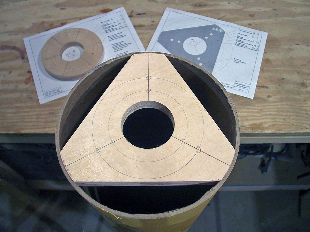
Before we go any further, we want to make sure the bottom part of the cell has a nice, snug, 'sliding fit' with the tube - it should be tight enough to stay put in the tube, but loose enough so we can slide it up and down the tube to adjust the mirror cell position while we are testing the optics before we screw it in tight. It should not distort the tube out of round.
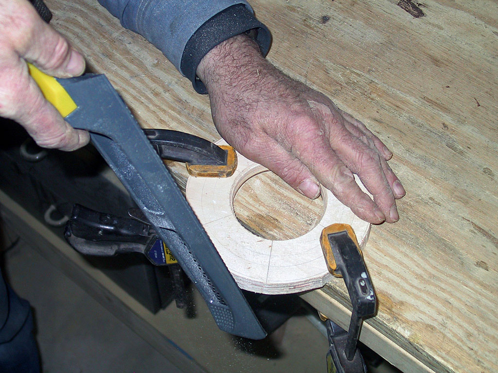
Test the fit. If you have measured carefully and rough cut to within 1/8 inch of the drawn line, it should not fit in the tube at this point. Shape the edge close to, but not quite up to the drawn circle, and test the fit again. Keep shaping until you get a snug, sliding fit. Shape each 'leg' equally, so you don't end up with a lopsided part.
The above 'shape slowly' is good advice. As shown in the photo, we did our initial shape to a little less than 1/8 inch of the drawn compass circle and then tested in our tube. The initial fit was actually just a bit looser than we wanted. Had we shaped right to the circle before the first fitting, the fit would have been very much too loose.
Completing the Top Part of the Mirror Cell
Now it is time to drill the holes for the push and pull bolts and their related hardware. We will use a spade bit to recess the tee nuts and washers to be even with the surface which allows the mending plates which the push bolts push against to partially cover the tee nuts in necessary (see photo below). It also makes the assembled cell a little bit thinner.
It is critical that the pull bolt holes in both top and bottom line up. If you have done a careful layout, this should not be a problem. If you are concerned about this, you might want to clamp the two pieces together, carefully aligned, and drill pilot holes through both pieces for the pull bolts. After you drill each hole, you can push a small nail in it, to keep the parts aligned while you drill the other holes. In all cases, but especially here, be sure to keep you electric drill straight and not drill angles holes.
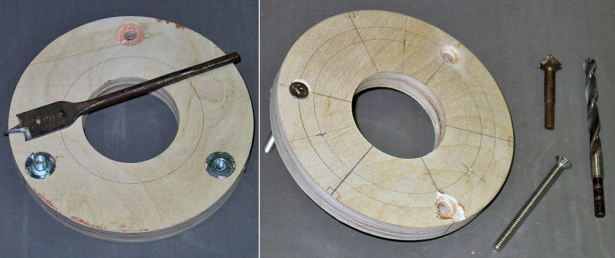
Starting with the mirror cell top, our wooden 'donut', we drill 1/8 inch pilot holes through the plywood for the pull bolts. Also, while you have the 1/8 drill handy, mark the locations of the mirror glue dimples by drilling just a little hole at their three locations if you haven't already marked them. Then, flip the part over on it's back and drill a recess for the three tee nuts with a ¾ inch spade bit. Drill slowly, stop after a little bit, place a tee nut upside-down in the recess and see if it is deep enough (it only needs to be about 1/16 inch deep. When you have all three recesses made, drill out the push bolt holes with a 5/16 inch drill. Then working again from the top side, drill out countersinks on these holes deep enough so that the pull bolt heads will sit just below the surface. Finally, install the three tee nuts, gently tapping them into place with a hammer, or squeezing them into place with a vise. In both cases, it helps to have a piece of metal on top of the tee nut to push them all the way into the recess - we used a ½ inch socket from our socket wrench set.
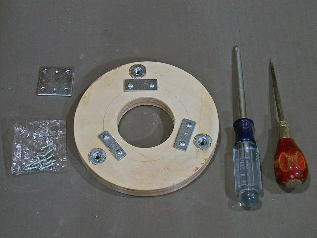
The only mending plates we could find were 1½ inches square, way too big for our little 6 inch mirror cell. So we cut them down to 1½ to about ½ with a hack saw, and then filed the sawn edges smooth. Install with wood screws along the compass line drawn to represent the push bolt circle, just under the tee nuts, so that the push bolts will press on the mending plates, not soft wood. Both the tee nuts and mending plates will stay in place when we paint this part black later. Now we move on to work on the top of this part.
Next we install the mirror side support brackets, which are metal corner braces. These are optional for 8 inch and under mirrors; the much heavier 10 and 12 inch mirrors absolutely need them. We will use them on our 6 inch because they are simple to do and it will show you how to install them. The primary mirror surface is fragile and should not be touched by anything (it might scratch or leave a greasy fingerprint which will be hard to remove). When you work with your primary mirror, as you need to do in this step, wear cotton or vinyl gloves and be very careful and protective of your mirror. We are going to cheat a bit on this, and use a 6 inch mirror blank, as we have them available, and we won't have to worry about damaging it. As a benefit, it is somewhat transparent and you will be able to see the mounting of the supports under it.
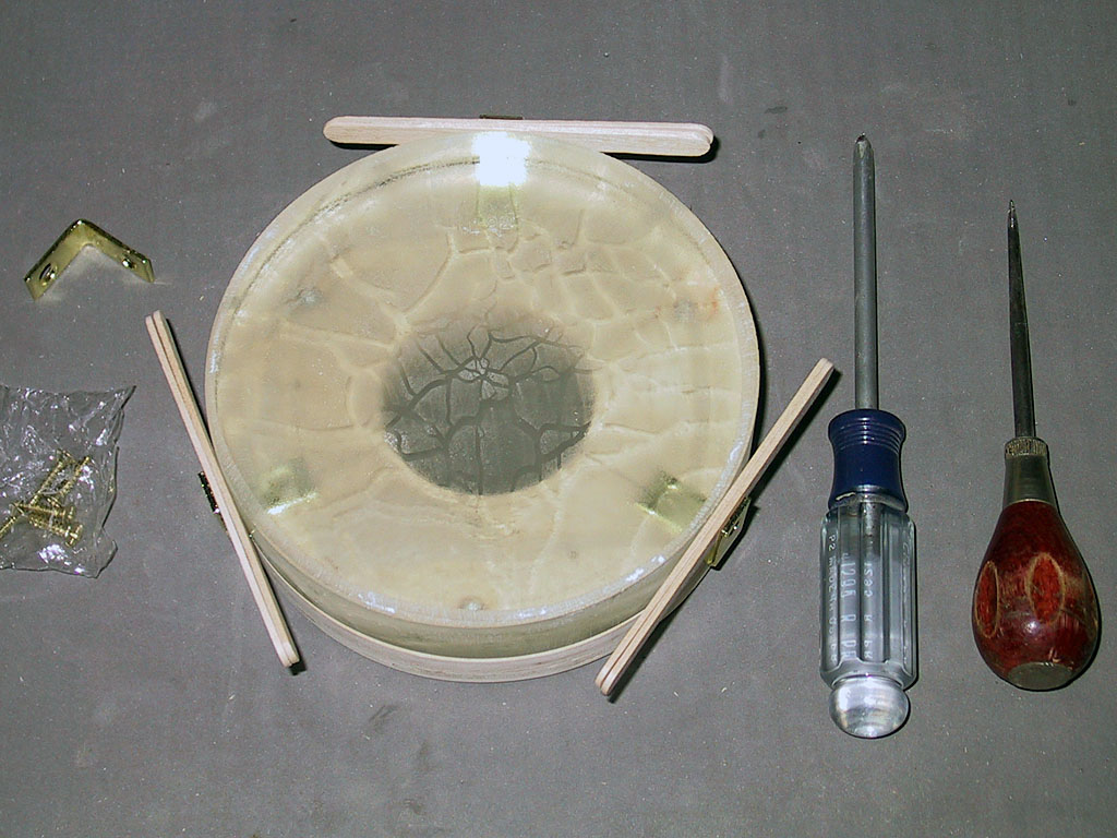
The side supports need to be mounted opposite each bolt hole and hang out over the edge of the cell just enough to allow approximately 1/8 inch clearance all around the mirror (The gap size is not critical, a little large is OK. Later, this gap will be filled with flexible silicon adhesive). Popsicles sticks are a wonderful item to keep in the workshop with many uses. Measuring two that we had on hand, the pair was 5/32 of an inch thick, just a bit larger than the 1/8 gap we desired, so we will use them as a gauge. Place your mirror on the cell top, center it, and then slide one corner brace underneath it, spacing it out the desired distance. Measure how far it hangs out. Then remove your mirror, put it in a safe place, and mount the three corner braces with this overhang. Once mounted, put your mirror back in the cell, and use the popsicle stick gauge or a ruler to check the gaps. Adjust if necessary. When you have this right, pack you mirror safely away, you won't need it again for a while.
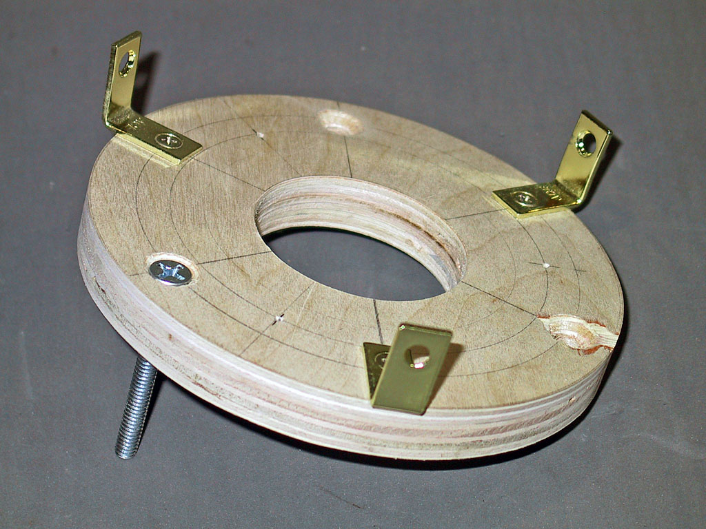
Finally, we screw the flat-headed pull bolts into the tee nuts and snug them up with a screwdriver. This completes the initial assembly of the mirror cell top, and it should look like ours in the photo. later we will remove the bolts and paint everything else flat black. But now, we move on to complete the bottom part, and do a test assembly of all the parts to make sure everything works as planned.
Completing the Bottom Part of the Mirror Cell
Now we complete the bottom part of the mirror cell. We'll give a little less detail, as we will use the same techniques we used on the top part.
First, drill 1/8 inch pilot holes for all six bolt holes - this locates the holes on both sides of the part. On the side that will face the top part, recess 3 areas for the push bolt tee nuts (inner ring). Then drill out all six holes with a 5/16 inch drill, and install the three tee nuts. This completes the mirror cell bottom.
Test Assembly of the Mirror Cell

Assembled Primary Mirror Cell
(Mirror Side Down)
Assembling the mirror cell is easiest with the top part facing down, resting on the side supports with the pull bolts facing up. On to each pull bolt, place a spring and then a washer (the tee nut below the spring also serves as a washer). Then, carefully slide the bottom part of the cell onto the pull bolts, with the push bolt tee nuts facing down. Onto the pull bolts place another washer, and then thread a wing nut on each (do not tighten). Finally, screw the push bolts into the push bolt tee nuts, but do not tighten them. Check that the mirror cell has enough play so that it can be tilted and tipped by squeezing near each bolt set, and verify you can slightly compress each spring without undue binding. If you do have binding, figure out what is sticking, and then try to make adjustments to unstick it - you may have to enlarge a bolt hole in one dimension with a coarse toothed round file, for instance. When everything moves OK, snug up the wing nuts, and notice the cell still is 'soft', the springs allow movement. Then snug up the push bolts, and notice how stiff the cell becomes.
This completes construction of the mirror cell. Next, we will do a partial disassembly and finish the cell.
Previous: The Primary Mirror Cell Next:
Finishing The Mirror Cell
Back to the Build a Dobsonian Master Index