

Building the World's Largest
Schupmann Telescope
by Scott Milligan, Springfield Telescope Makers
Page 4 of 7
Polishing Continued
Polishing continued until all signs of pits were removed. Now it was time to measure radius of curvature. The concave surface of the corrector posed no unusual problems, and was accurately measured on the radius bench. The convex surfaces were then compared against the concave halves of the recently finished test plate sets.
Here, I must digress for a moment to recall that there is nothing quite like the feeling one gets in the pit of the stomach while lowering a 13 pound full-thickness Pyrex disk onto the naked and defenseless surface of a large and (in your eyes) priceless optic. The only other feeling that remotely matches this one is the feeling you get while engaged in removing said test plate after the test is complete. It would be hard to overestimate the amount of force that must be applied, in a perfectly controlled manner, to achieve this second, unwanted task. If all that I have said above is not enough to turn the reader against the use of mammoth test plates, consider this: after all is said and done, the amount of additional, reliable information that is gained by using a test plate larger than six or possibly eight inches diameter is (almost without exception) exactly nil. That is because the increased weight and thermal mass of the larger plate introduce distortions in the test patterns that more than offset the largely theoretical advantage of greater aperture coverage. These distortions were large enough that examination of the fringe patterns during the fabrication process could not reveal whether the residual errors were due to test-induced distortions, or were actually in the glass. Further progress could only be made by conducting an optical test of the entire system.
Mechanical Parts for the Tube Assembly
Almost as soon as Phil and I had decided that the project would go forward, I began laying out the tube assembly, and producing detail drawings of the mechanical parts. One of the first tasks was to design lens cells to hold the optical elements.
on Hal's lathe.
The basic layout for the field mirror and corrector cells closely follows the schematics shown in Daley' booklet, with three fine adjustment screws opposed by tension springs at the corrector cell, and two orthogonal adjustment screws and a center pivot at the field mirror. 6061 T6 aluminum was chosen as the material for its ready availability, ease of work, reasonable cost, and good strength to weight characteristics.
The inside diameters of the cells were oversized to allow for insertion of plastic shims, which would prevent metal to glass contact. The faces of the internal shoulders and of the retainer rings were to be eventually covered with strips of self adhesive Teflon tape for the same reason. Retainer rings were designed to attach with screws, to avoid the problems that can occur with trying to match large diameter threaded rings and cells. Stainless steel inserts were added to prevent the relatively hard ends of the steel screws from galling the aluminum cells.

Through word of mouth I had learned that the Amateur Telescope Makers of Boston possessed an unusually resourceful member, and long-time telescope nut by the name of Hal Robinson. When I called to ask whether he would be interested in helping our little project, his answer was "it sounds interesting. Why don't you bring the drawings down to my house and we'll look them over together?" After seeing the drawings, Hal wasted no time in making suggested improvements, and began planning how he would use the machinery in his basement shop to make the parts.
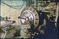
The cells for the two smaller optics were straightforward jobs for his milling machine, but the cell for the large lens was bigger than his existing lathe could handle. "But you know, I've been working on rebuilding another lathe," he said, "it's over a hundred years old, but I have a 24" diameter face plate for it, and if I just jack the head stock up about six inches, I could swing up to 24" diameters." Figure 7 shows the results of Hal's handiwork. In order to produce accurate reference surfaces that could be clamped to the face plate, the part was first rough machined, and then the external surfaces front and rear were lapped flat on a large flat iron grinding tool. The part was then returned to the lathe, and the final dimensions were accurately cut. By spring of 1988, the lens cells were finished.
Page 1 Page 2 Page 3 Page 4 Page 5 Page 6 Page 7
Back to the McGregor-Schupmann Page