
Building the World's Largest
Schupmann Telescope
by Scott Milligan, Springfield Telescope Makers
Page 5 of 7
The First System Test
An auto collimation test of such a large optical system posed the practical difficulty of finding a vibration-isolated test bench large enough to host the test. Fortunately, such a bench existed at OSTI, and with proper planning, we figured that our setup could be built, evaluated, and torn down in a matter of a day, or at most, two. The bench was an old cast iron lathe bed that had a 12' long x 4' wide 1" thick aluminum plate fastened on top of the ways. This arrangement was far from ideal from a vibration isolation standpoint, but it was the only available test space large enough to do the job. I quickly constructed makeshift plywood test stands to hold the optical elements that were mounted in their cells. The convex surface of the L2 corrector was given a temporary silver coating, and the lens elements were loaded into their cells.
When the alignment of the first system test had been optimized, a rather severe three point astigmatic pattern was observed in the interferogram. At that point, we did not have any conclusive evidence which pinpointed the surface or surfaces that were to blame, but it was logical to suspect the convex surface on the L2 corrector, since this is by far the most sensitive surface in the design. To check our assumption, the L2 lens was rotated 60 degrees, and when the three point pattern was also observed to rotate, we concluded that the source of the problem had been identified. But how could we fix it?
We were unable to leave the system test standing on the bench, and the test plate match was not sensitive enough to judge when the convex surface of the corrector was good enough. We needed another test that would be simple to implement, would occupy little space, and would give unambiguous results. Enter the Ross null test. Peter Ceravolo and Dick Stoltzman had just recently published their thorough investigation of this test for amateur use. Since the Schupmann's L2 corrector lens, when tested by itself, created over-corrected spherical aberration similar to that imparted by a paraboloid tested at center of curvature, I reasoned that a Ross null could be found for testing the corrector lens. A few hours spent playing with the concept using Don Gibson's OSDP program confirmed my initial hypothesis; a two inch diameter plano-convex lens made from Bk7 would make a excellent null for our corrector.
null lens
Phil and I proceeded to make the null lens from a blank donated by OSTI. Meanwhile, Phil also continued to work on smoothing the figure of the convex surface of the corrector. He found that the extreme figure accuracy required, combined with the relatively thin aspect ratio (approximately 11:1) meant that the lens could no longer be mounted to its holder using masking tape around the perimeter. Instead, the concave surface of the lens was mounted to the convex tool by forming a multitude of pitch "buttons", each about 3/8" diameter, which were arrayed across the face of the holder, and then the lens was pressed gently onto the buttons while they were still warm enough to conform to the surface and adhere to the glass.
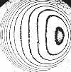
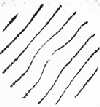
At last the null lens was finished, and we prepared to have our first look at the corrector as a stand alone item. After scrounging a few necessary parts, we found the Ross null test to be simple to set-up, align, and interpret. Figure 9 shows an interferogram taken without the null lens in place; the L2 lens shows about 5 waves of spherical aberration. Figure 10 shows the interferograms taken through the first null test; notice that a central defect is revealed, but that the three point astigmatism has been removed.
Page 1 Page 2 Page 3 Page 4 Page 5 Page 6 Page 7
Back to the McGregor-Schupmann Page