Build a Mirror Tester
A Foucault or Knife Edge Tester and Ronchi Tester
Page 2: Head & Setup Aids
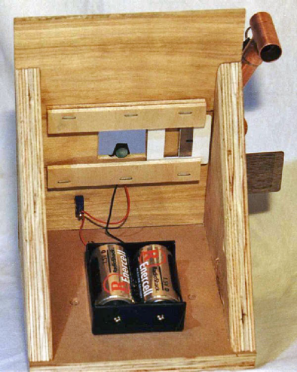
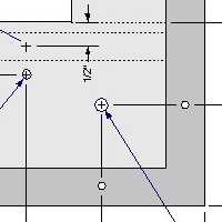
 Dimensioned Head Base Plans
ABOUT THE TEST HEAD: The head will sit on top of the stage - it holds the light source,
knife edge, (optional) Ronchi screen and (optional) setup aids. The large area surrounding the viewing hole
provides a target surface for alignment - the returned beam will likely reflect off this surface and the mirror
stand can be adjusted until the returned beam is in the viewing hole just above the light source. The knife
edge is mounted in a standard 2" x 2" slide frame (shown at left), and a Ronchi screen can be mounted in one
also (not shown). The sliding track allows a clear aperture for a knife edge or a Ronchi screen to be quickly
positioned and used.
Note: The light source and knife edge should be just about at the same level as the center of the
mirror under test. The dimensions used here for the test head were sized for our matching
Mirror Test Stand. If you are using a different stand, you should adjust the
size of the head appropriately.
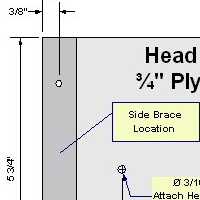
CONSTRUCTION: Tester Head
Referring to the Head Base Plans,
start by cutting the plywood base and the two triangular side braces. Drill four 1/8" pilot holes for the brace
screws, and two 3/16" holes for the screws that will attach the head to the stage. Put these parts aside while
we build the Head Face.
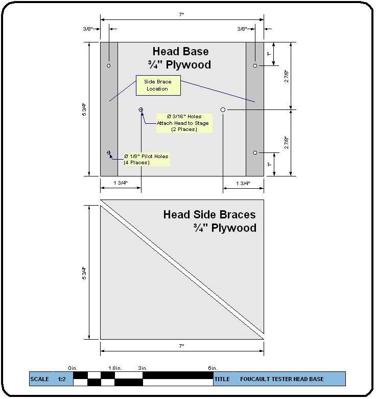
 Dimensioned Head Face Plans
The Head Face is a built from a sheet of 1/4" plywood - refer to the
Head Face Plans. It has a couple of tricky parts. The central square viewing opening should be tackled first.
Mark it on the plywood, then drill four large holes (about 1/2" each) just inside each corner of the opening.
You can then use a keyhole or jig saw to cut out the square.
ALTERNATIVE KNIFEDGE ATTACHMENT: If you don't want to make tracks
or use slide frames, you can just tape (use duct tape) or screw a knife edge over the viewing opening. Do
this after you mount your light source, so that you can be sure the knife edge "cuts" (partially covers)
it. A utility knife blade is longer than a standard razor blade and is better for this use. You can also
tape or screw a Ronchi screen over the viewing hole - just get it flat.
The second tricky part is the pair of tracks used to hold 2" square slide frames (these in turn
can hold knife edges and Ronchi screens). These are optional - see the box at left
for a simpler way to hold a knife edge. The tracks are are also made from 1/4" plywood. Make them short enough
to fit between the side braces. Glue them with wood glue, and use short brads or staples to hold them in place
while the glue dries. It is a good idea to have a slide frame handy to adjust clearances while doing this.
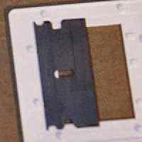
KNIFE EDGE ASSEMBLY: Our knife edge assembly is made from a standard 2" x 2" plastic
slide frame, sold in photography shops to mount 35mm slides in. Click on the image at left to see several steps in making this assembly.
A standard single-edge razor blade is just the right size to fit in this frame. But first, you must carefully
remove the stiffener opposite the blade edge. Leave the cardboard guard on the blade and wear gloves, or mount
the blade in a vise. Then use a tool to pry the stiffener open and then off the blade - we used a small pair
of diagonal wire cutters. The bare blade is then placed in the frame and the frame snapped shut. Black tape
is used to keep the blade from sliding in the frame, and to optically darken the flat part of the blade and
the white frame.
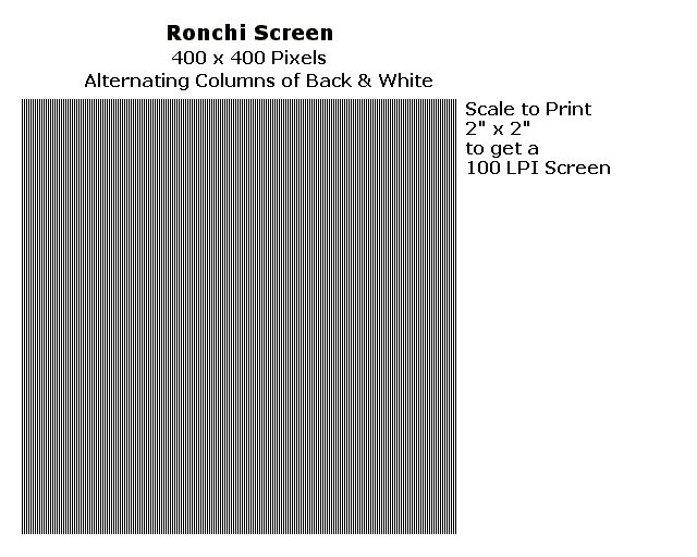
RONCHI GRATING: Glass Ronchi screens in 2" x 2" size can be
bought and will slip right in the track assembly; Film type screens can be bought and
often come in slide holders; see our ATM Suppliers
list for vendors. You might want to consider
RonchiScreens.com if you are looking for an inexpensive film screen. See our page on
Reading Ronchigrams for advice about the number of line
per inch to use, although 100 LPI is a pretty good general purpose size.

A film type screen can be made on a computer printer using overhead transparency film. Cut the
film screen to size and mount into a slide frame also. Generally, screens between 80 to 150 lines per inch are
used; 100 LPI is a good first choice. Select the Ronchi Screen image on the right for a
Printable Ronchi Screen Image (We set
Fire Fox 3.6 to scale the page image in Page Setup to 48% to get a nice clean 2"x2"
Ronchi Grating on our HP LaserJet 2200D printer). Update added in January 2011:
While the previous screen image worked on older operating systems and printers, it is
getting harder to use now. We suggest you might want try this PDF file first:
atm_ronchi_screen.pdf. Open it in a PDF
viewer such as Adobe Reader or Foxit Reader, use print preview to make sure you print it
at no magnification or scaling, and it should give you a good result. The file is set up
for 200 pixels per inch.
HEAD ASSEMBLY: With all four parts cut out and drilled, assembly is simple. The side braces are glued
and screwed onto the base. Slide you knife edge and Ronchi screen into the tracks on the face - make sure the
knife edge and Ronchi bands are vertical. The face is just screwed on, not glued, so it can be removed
for access to the items in the track. Screw the face on before the glue for the side braces sets, to make sure
everything lines up and is square.
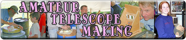
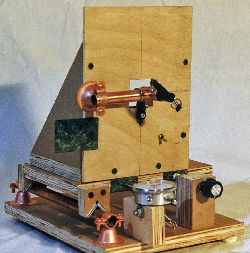
OPTIONAL SETUP AIDS: We present two setup aids: (1) a tape measure hook; and (2) a miniature flashlight holder. When
working by yourself, these simple items can make setting up and aligning the tester much easier.
Tape Measure
Hook: Our Mirror Test Stand is shown with an optional
tape measure attached. It is convenient to be able to hook the end of the tape onto the tester head, so your
hands are free to move the mirror stand to the proper radius of curvature for testing. Our tape measure hook
can be seen sticking out from on the left side of the photograph at the left. It is simply a countertop laminate
sample (which comes complete with a pre-drilled hole) screwed to the back of the test head. The screw is tightened
just enough to hold the laminate in position, yet it can rotate down and out of the way when desired.
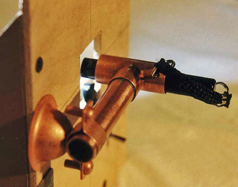
Flashlight
Holder: The flashlight holder is shown in the photos above. The knife edge and/or Ronchi screen have been slid out
of the way, the copper pipe holder has been rotated in front of the viewing hole, and a miniature flashlight
has been inserted and aimed at the mirror. While the green LED is plenty bright enough for testing and aligning
an aluminized mirror, it does not produce enough light to align an uncoated mirror. To use, you would aim the
flashlight beam at the center of the mirror, and then adjust the mirror stand to return the beam directly back
to the flashlight. The roughly aligned reflection can be easily seen on the face of the head. Several
club members have used a pocket laser pointers instead of a flashlight with good results also. The holder is
built from a Copper Van Clamp, a short length of 1/2"
Copper Pipe, and a 1/2" Copper Tee. Solder or glue the pipe to the tee, mount the Van Clamp just tight enough so
it can be rotated out of the way, and clamp the pipe just tight enough in the clamp so it can be rotated (altitude
adjustment for the light).
This completes mechanical work on the head. All that remains is to construct and install the LED illumination
source, which is described on Page 3: Electrical, and then attach the head to the stage.
When the electrical work is complete, you should attach the head
assembly to the stage using two screws through the 3/16" holes in
the head. I used 1¼-inch drywall screws to do this, offsetting the
head slightly to left, away from the adjustable foot side.
|