|
|||||||||
Build an Adjustable Mirror Test Stand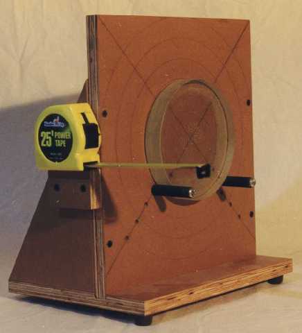
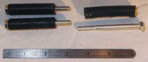
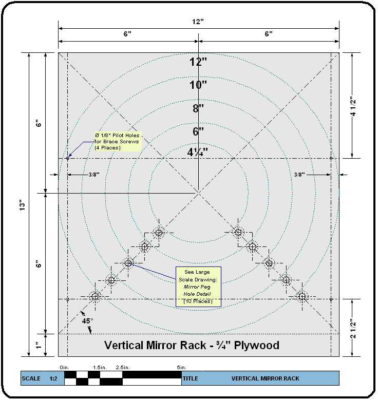
The Mirror Stand shown here can adjust to mirrors from 4" to 12" in diameter. It is made from four pieces of 3/4" plywood and a few odds and ends from the hardware store. It is shown holding a 6" mirror. Also shown is an optional ruler that has been attached to the stand to make setup and radius of curvature measurement easier. DESIGN CONSIDERATIONS: A mirror stand must be able to firmly hold the mirror at a height compatible with your tester (for an adjustable stand like this one, the tester is usually built to match the centerline height of the stand, which is typically higher). The test stand must be able to aim the mirror in Yaw (Left to Right) and Pitch or Tilt (Up and Down). In this design, yaw is handled by twisting the whole stand left or right. Pitch is handled by an adjustable rear leg, clearly seen in the rear view photos. Keep the mirror between the front an rear legs! You might be tempted to shorten the base such that it does not project forward of the vertical board; however this would put the weight of the mirror in forward of the front legs, and the stand might disastrously (for your mirror) tip over (the stand will survive!). CONSTRUCTION: The test stand can be built from a 12" x 30" piece of 3/4" thick plywood. Shown is MDO plywood, which has one surface ply made out of hardboard; you can use any plywood which is flat and has a smooth surface to rest the mirror against, such as the commonly available A-C grade (the "A" face is smooth and without large knots or voids). Cut and lay out the Mirror Vertical Rack first (Test Stand Plans Page 1). Drawing directly on the plywood, first lay out the two 45° (diagonal) lines to find the center, and then using a compass draw the mirror circumferences. You need to know the size of your pegs before you can lay out the peg holes. Our mirror pegs were made from 1/4"-20 hex head bolts, 3" long, covered with 1/2" outside diameter, 1/4" inside diameter rubber hose bought at an auto parts store. You might also use clear vinyl tubing, which is available in many home centers or hardware stores, but it will likely have a thinner wall.
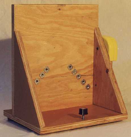
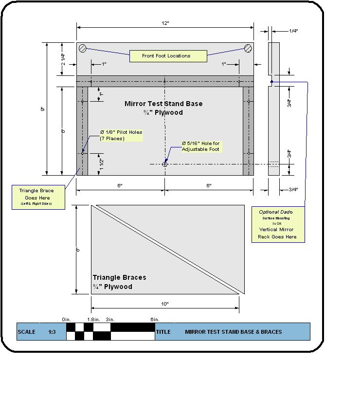
Now lay out the locations for the mirror peg holes (Test Stand Plans Page 2). The peg holes should be centered on the diagonal lines, such that the peg surface and mirror edge will just touch. Therefore the peg hole center should be located outward exactly the radius of the outside diameter of your peg, which in may case is ¼" as I am using ½" diameter hose. Drill ¼" holes for the mirror pegs from the front of the Mirror Vertical Rack board, then flip the board over and counter bore with a 5/16" drill just deep enough to accept the Tee-Nuts. Experience shows that you need the support of the plywood at the front, so keeping the front of the hole at ¼" is important to keep your mirror pegs from drooping over time. Also drill the four 1/8" pilot holes, and countersink them so that the screw heads will be below the surface (the mirror must lie flat against the rack in use). With all the holes drilled, you can hammer the Tee-Nuts into the back of the mirror board - try to make sure they lie flat, so that their threads will be perpendicular to the plywood. Next, it is time to cut out the base and two triangle supports from the remaining plywood (Test Stand Plans Page 3). The photographs show a dado (slot) in the base to accept and align the vertical mirror rack - this is entirely optional. If you don't make a dado, you might want to clamp a piece of scrap wood to the base to help position the vertical mirror rack during assembly. Drill the seven 1/8" pilot holes for the screws and a 5/16" hole all the way through for the adjustable foot. Then hammer in a Tee-Nut into the bottom of the base for the foot. Assemble the stand with yellow wood glue ("Carpenters Glue") and screws. Drywall Screws are thin (helps to prevent splitting the plywood), grab well, have flat heads, and are flat black (won't reflect light). You might want to clamp any plywood that is being screwed from the edge to help prevent splitting. Assemble the two square pieces first, then the support triangles. Do this all at once before any glue sets to ensure a good, square fit. After the glue dries, you should seal the stand to protect it from moisture. You can use paint or a clear sealer such as polyurethane. To finish, attach two feet to the bottom of the front of the base. Find feet that are at least a 1/2" tall, as they need to be tall enough to allow the stand to tip back a bit, and the adjustable foot will be at least 1/4" high. The adjustable foot is made from a 1/4" x 2" Carriage Bolt and a Radio Knob. Make sure your bolt head is smooth; some have embossed lettering that should be filed off. Screw the Carriage Bolt up from the bottom so that the bolt head becomes the foot, and attach the Radio Knob to the protruding end of the bolt. Screw in the mirror pegs and your mirror test stand is done! |
|||||||||
|
|||||||||
