|
||||||||||||||||||||||||||||||||
Build a Mirror Tester
|
||||||||||||||||||||||||||||||||

| Digi-Key | ($5.00 handling charge for orders under $25.00) |
 |
| Jameco | (No minimum order if done on the Internet) | |
| Mouser | (No minimum order) | |
| RadioShack | (No minimum order) | |
| Super Bright LEDs | (Minimum shipping fee of $5.00 for Internet Orders) |
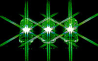
Brien Stratton wrote that he successfully used a Mode Electronics #55-555HB green LED with 900 to 1500 mcd brightness. Because this is so bright, Brien added a 100-ohm potentiometer (variable resistor) in series with LED so he could dim it to comfortable levels. You still need to include, in series, the fixed current-limiting resistor, which for this unit he calculated to be 5 ohm (Brien used two 10 ohm resistors in parallel to get this value). Check the Mode Electronics web site to see if a local distributor is in your area.
Other ideas if you want to buy something locally:
- Use a mini-Maglite® bulb which you should be able to buy a local hardware or discount store.
Wrap bulb with "invisible" tape to frost it and diffuse the light. Mounting is left as an exercise for the
inventive ATM. No resistor needed.
- Drill a hole in the side of a mini-Maglite® so that the light from the bulb shines out through
it (better remove the bulb when drilling :-) ). Blacken the normal beam exit, and use clear "invisible"
tape over the new hole to diffuse the light. Mount the assembly using cable clamps or cable ties, allowing
room to rotate the nose piece which is also the switch. No electrical work is necessary for this design.
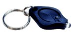 Remove
the super bright LED from one of the keychain style flashlights, such as those made by Photon, Princeton
Tec and others. Note that these normally run on small "coin cells" and do not included a current-limiting
resistor. This is probably because the coin cells have sufficient internal resistance to limit the current.
If you hook such an LED up to a bigger battery, such as a pair of AA or larger batteries, you may need to
include a current-limiting resistor. Since these LEDs should be more than bright enough, I'd suggest inserting
a 5 to 10 ohm current limiting resistor in the circuit if you plan to use large batteries.
Remove
the super bright LED from one of the keychain style flashlights, such as those made by Photon, Princeton
Tec and others. Note that these normally run on small "coin cells" and do not included a current-limiting
resistor. This is probably because the coin cells have sufficient internal resistance to limit the current.
If you hook such an LED up to a bigger battery, such as a pair of AA or larger batteries, you may need to
include a current-limiting resistor. Since these LEDs should be more than bright enough, I'd suggest inserting
a 5 to 10 ohm current limiting resistor in the circuit if you plan to use large batteries.
Nose and Chin Room
The tester was designed with a large flat panel on the head to facilitate initial alignment when working alone. However, some people find it somewhat difficult to get your eye really close to the knife edge, as your nose, chin (and beard in my case) tends to bump into the back of the tester. Not surprisingly, some people choose to modify the tester to avoid this clearance problem. Michael Burr wrote to me that he now uses this design:
"There are many possible approaches to a better Knife Edge/light-source holding design, but the one that worked for me is to take a thin piece of aluminum sheet, about 2" wide by 6" tall, and screw it to the right-hand upright support in place of the 1/4" plywood. Then attach revised (shorter) sliders to accommodate the Knife Edge and Ronchi slides, and affix the light source to the lower slider in the same manner as prescribed on the original design.
"If the now-single upright support isn't sufficiently sturdy, it might be necessary to brace it with a small triangle of wood at its base. But otherwise the left upright support basically becomes superfluous in this design revision..."
Another approach is just move the knife edge and source to one edge of the test head, or cut away a portion of the flat panel for nose clearance.
Alignment Laser Idea
Barry Jensen of Windham, NH writes that he used a punch to dimple the copper pipe that holds his alignment laser. He can then push the laser on button under the dimple to hold it on while he lines up his tester.
Notes on Using the Tester
Eventually, there will be a complete page devoted to testing procedure. But for now, I'll put answers to common questions here that I receive through e-mail or in person at convention or our mirror class.
How Much of the LED should the Knife Edge Cut?
The simplest and most direct answer is half; Center the knife edge on the LED. As you will find, this is not a critical adjustment, and you can control the overall mirror brightness by varying how much of the LED you cover with the razor blade. But novices should start with approximately half the LED covered, and they should be able to get a clean, bright image to work with.
How do I use the Ronchi Grating?
Center the Ronchi Grating over the backboard opening, so the the entire LED shines through it. The grating should be oriented with vertical lines. You will find it is easier to set up and align the tester with the Ronchi grating, so you may want to start out using it. When you are exactly at Radius of Curvature, there will be one dark and one light band on the mirror. If you are inside or outside R. o. C., then there will be more bands the farther away you are.
Most Ronchi testing is done inside R. o. C. so that five to fifteen bands are visible on the mirror. Perfectly straight bands indicate a perfectly spherical mirror. Using the stage tilt adjustment, you can make the bands scroll horizontally over the mirror, which makes subtle curves in the bands easier to see. Edge defects are common, and the Ronchi test is excellent for highlighting these defects. With the Ronchi Screen Inside R. o. C., bands that hook inward toward the center of the mirror indicate turned down edge, if they hook outward you have a turned up edge. It is hard to make quantitative test with the Ronchi Screen, and to measure parabolas - use the Foucault test for this.
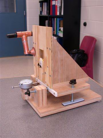
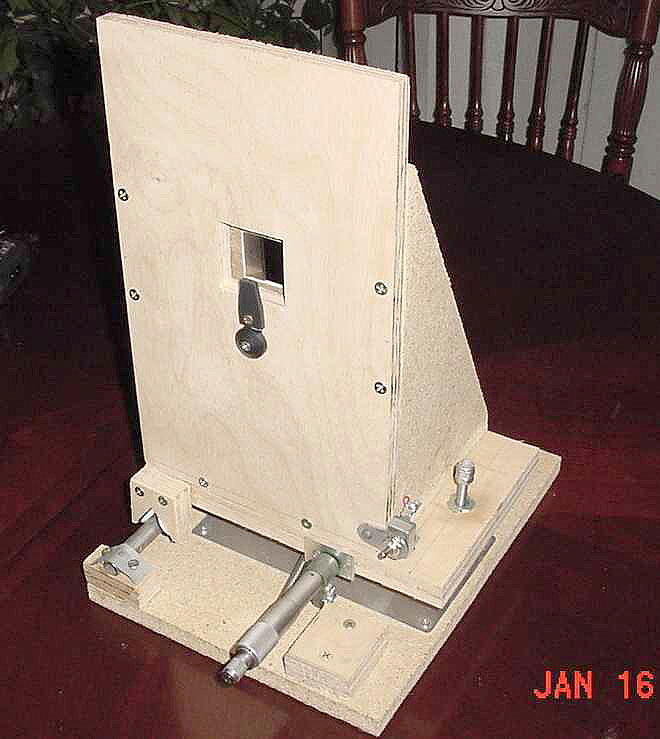
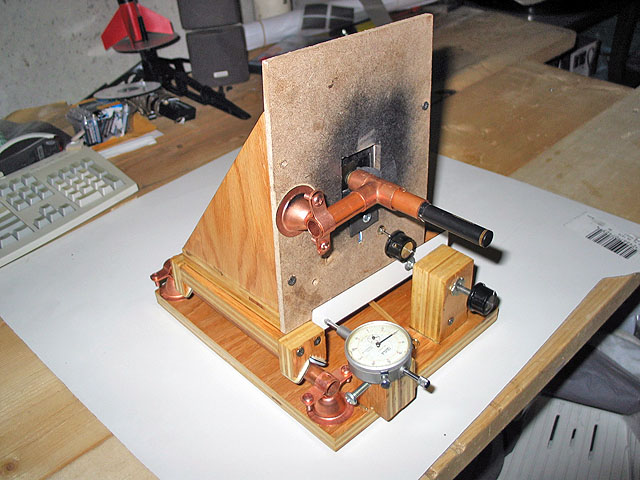
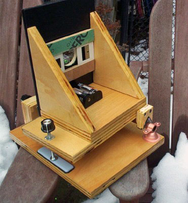
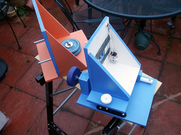
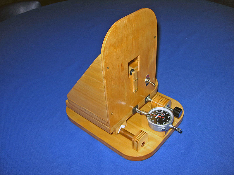
Photo Gallery
Have you built a Stellafane Tester? We'd love to see a picture of it. E-mail a photo of your version to the webmaster using the link in the page footer below. We will publish the photos here.
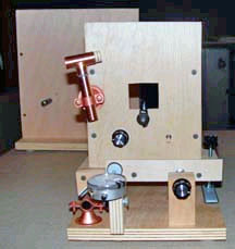
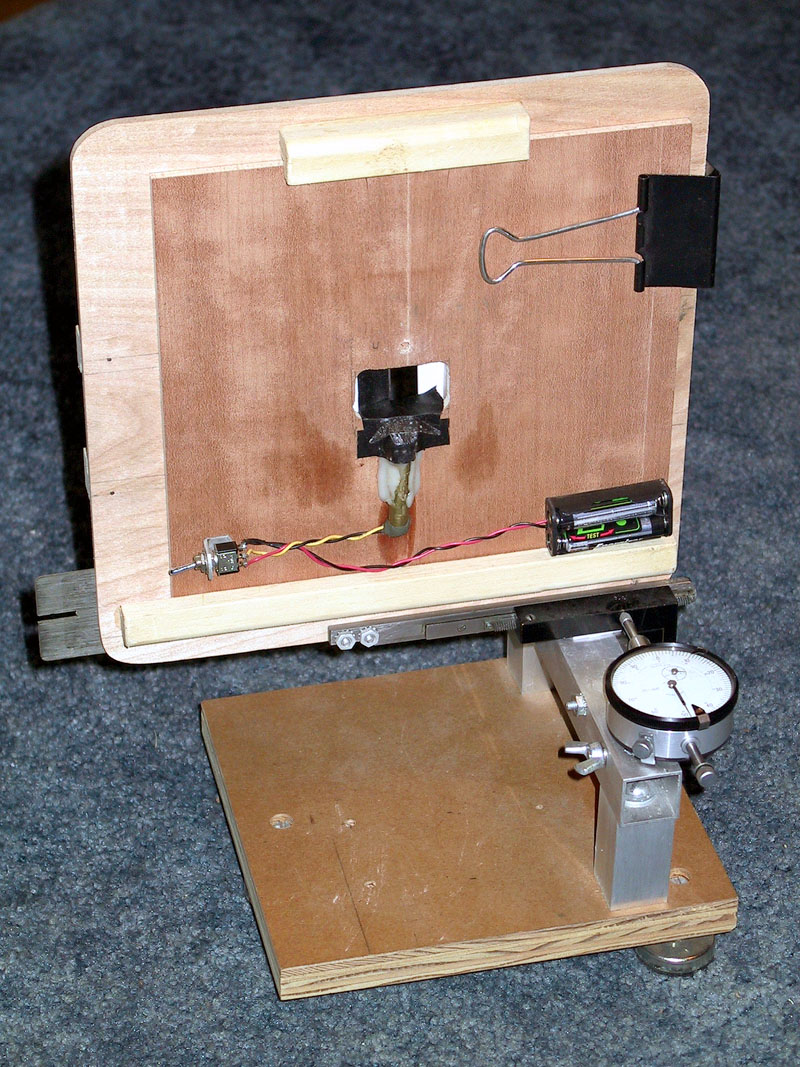 Ken Slater's tester, the precursor of the Stellafane Tester, uses a surplus microscope X-Y stage |
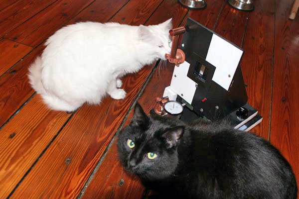
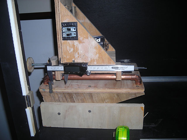
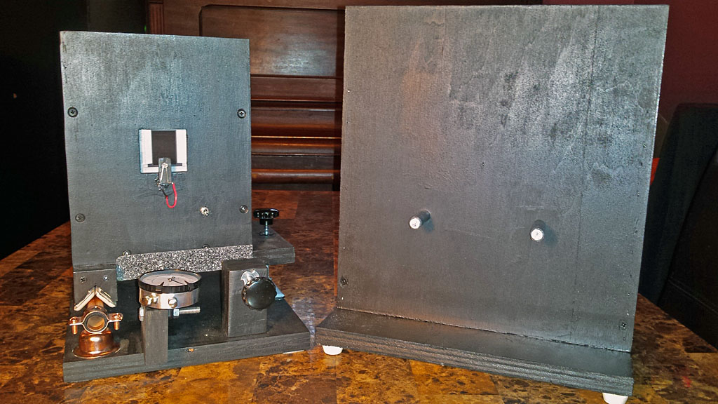
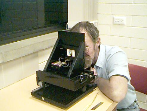 Whyalla Group's Black Tester Astronomical Society of South Australia |
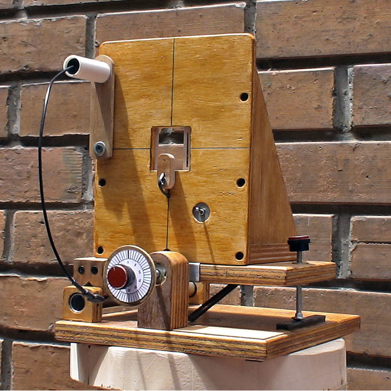
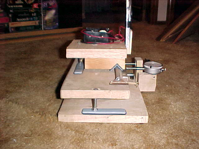 Joe Mirando's Tester With independent X-Y stages and reduced head width |
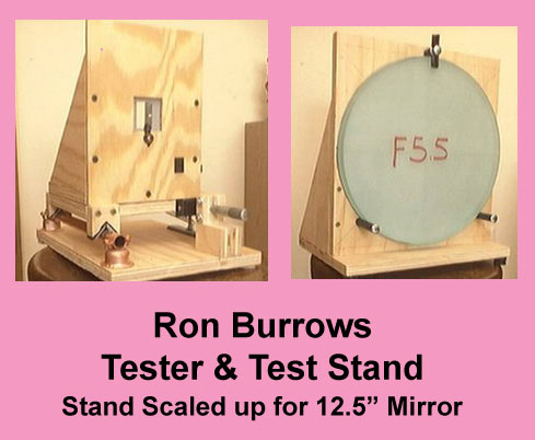 Ron Burrows' Tester & Stand With Stand for 12.5" Mirror |
 Fred Bancroft / John Stetson Portland, ME |
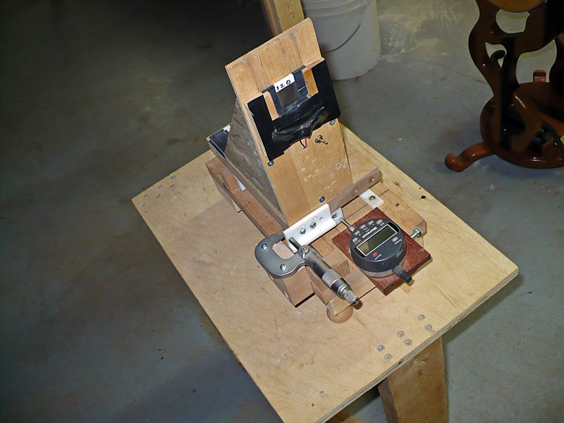
 Rodney Mayes, Kentucky Micrometer drive, Sized for a 16" Mirror |
 Barry Jensen Windham, NH |
 Jay Drew East Lyme, CT |
 Bill Sweeney Shoeburyness, Essex UK |
 Fran Edwards Worcester, MA |
 Daniel Valverde Montclair, NJ |
 Normand Fullum Montreal, Quebec |
 Andy Johnston Newtonville, MA |
 Jeff Parenteau Gilsum, NH |
 Juan David Barrada Medellín, Colombia |
 Dan Williams Liverpool, NY Nice protrusion for the knife edge to make nose room! |
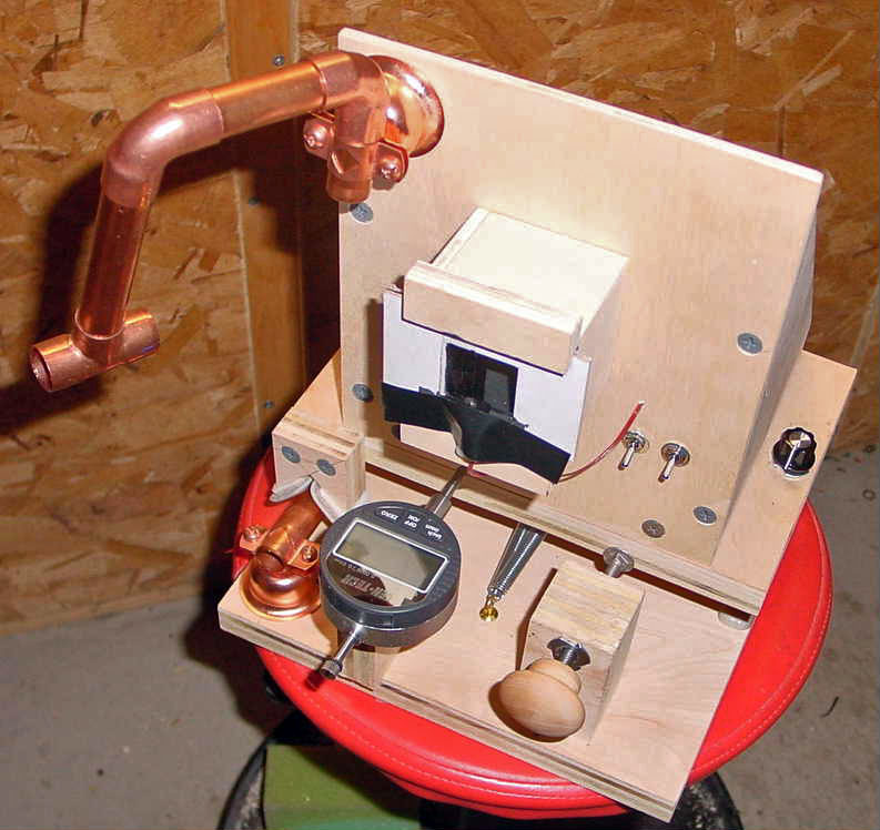
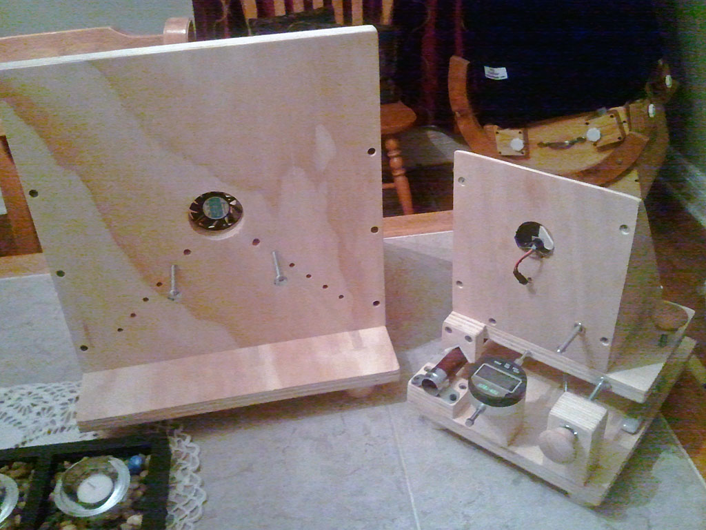 Ryan Goodson Syracuse, NY Fan helps cool mirror down faster for testing |
 Torsten Mellenthin Bonn, Germany |
 Alexey Bobkov San Jose, CA Added removeable upper rail |
 Salvatore Antonio Spampinato Vicenza, Italy Vertical Lamp with 45° Aluminum Foil Reflector |
 Pete Mulka Dearborn Heights, MI All black and faithful to the plans |
| Test Equipment Page Navigation |
ATM Index | Tester 1 Base & Stage | Tester 2 Head | Tester 3 Electrical |
| Test Equip. | Tester 4 After Thoughts | Tester 5 Parts | Tester Stand |