|
by 'Diesel' Dave Aucoin of Waltham, Massachusetts
2000-Oct-18
For as long as I can remember, I have always wanted a simple set-up telescope, easy take
down, easily transportable with a no-tool set-up. I also wanted a telescope that had a low center of gravity, so
I didnt have to stand up very high or on a stool to look in the eyepiece. It had to be lighter in weight than
its predecessor and be something that was eyecatching as well. The result is what you will see in the next few
pages. I could not have had as much fun when building this scope as I have had when making other scopes or at
least re-designing them as well.
I had read every article about the Obsession line of telescopes, the Starmasters, the
Tectrons with ease of set-up and breakdown and transportability. I didn't have the large budget to spend on any
of those higher priced, but finely crafted scopes, so I redesigned the Coulter. It took me 2 months to build of
4 and 8 hour daily sessions in the workshop while I was recovering from an illness and about $1400 in cash for
wood, hardware and more hardware, plus the spider, diagonal, diagonal holder, truss tubes, primary mirror
holder, focuser, 8x50 finder and Quik Finder, truss tube covers, power tools that I didn't already have and stain
and polyurethane.
I spent another $1600 on eyepieces, filters and Star Atlases, which I will mention after I
tell you how I built the scope.
Although listed above, these are the criteria I needed in the scope to be built:
- Light in weight, one person set-up
- No Tool set-up and take down
- Easy to transport
- Few components, easily stored
- Nice to look at
- Radical design
- Contemporary features
- User friendly
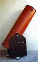
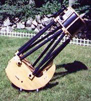
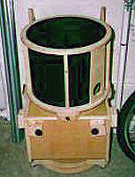
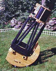
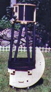
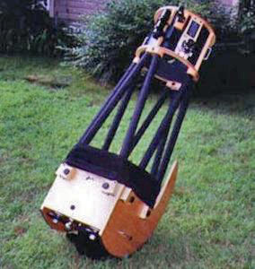
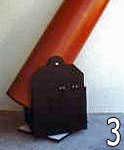
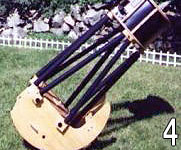
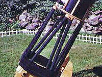
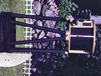
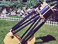
Photo 3 shows an original Coulter Odyssey I. Photo 4 shows the same scope minus
everything except for the primary mirror. That's right, I re-designed the scope to fit the above criteria. I
saved weight and gained portability, lost the bulkiness and gained easy breakdown and storage. It goes together
with nothing except what is shown and I do not need any tools to set it up.
I saved about 35 Lbs. in weight over the original Coulter scope. Most of the weight of the
original is in the rocker box, with heavy thick particle board. The tube was heavy too. My scope I cut the
rocker box down to practically nothing and made the center of gravity about 1/2 of what it was of the original.
Viewing height is about 68" off the ground.
Set up time is about 6 minutes and after collimation, only 10 minutes have elapsed (if it
needs collimation). Cool down time is greatly reduced , due to the truss tube design and a fan on the bottom.
The Layout
I purchased a sheet of ¾" Baltic birch furniture grade plywood. Technically it is called .7
inch thickness. I obtained it at a local Home Depot (plug). Getting it home was another problem. It was a 4 X 8
sheet and my car could not take the uncut sheet, so we had it cut to 2 equal 4 X 4 sheets. It still didn’t fit,
so I shaved off 10" from both pieces. When I made the drawings, I had a specific layout in mind. I thought I had
just blown the project by not having the right sizes to make the pieces I needed. Well, after getting the wood
home, I started to measure out the pieces I needed by taking the dimensions I knew and plotted them out on the
plywood. I managed to get to sides of the mirror box and front and rear mirror box pieces penciled in. Now the
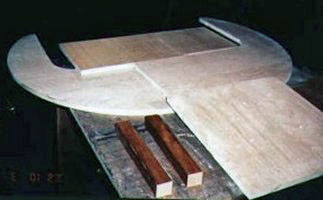
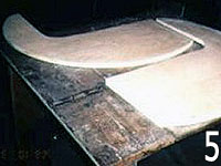
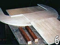
design is a radical one. Photo 5: 2 sides to the mirror box. Photo 6: 2 sides plus the front, rear and
bottom board and 2 inside supports later discarded.
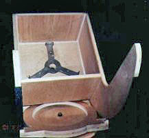
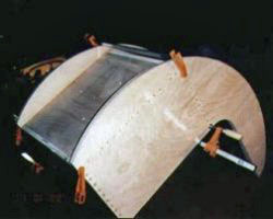
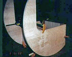
Mirror Box
The bearing/mirror box is an 18" radius, as was the mentioned in the web page that the radius
he had was 18". So I drew the design out, using a 36" circle and cut it out using a friend’s router, getting 2
identical pieces. I cut it out with a jigsaw and I sanded the edges and the surface. Next I used a table saw to
cut out the front and rear panels. Then I cut out the first of 2 designs for a spreader bar. Just in case
someone bumped into the extended bearings that protrude beyond the mirror box, I wanted to insert the spreader
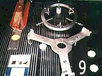
bar to prevent that and reduce flexure. I had also routed out the circle design for the rocker box and ground
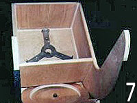
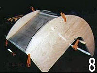
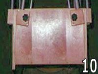
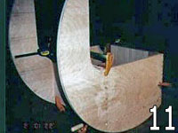
board, which I will talk about shortly. Photo 7: Just removed the clamps. Photo 9: Mirror holder. Photo 8: Just assembeled the bottom board.
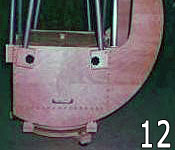
Photo10: Mirror box rear. Photo 11: Side and front and rear boards glued, screwed and clamped. Photo 12:
Mirror box side.
The mirror box had an inside dimension of 16.5" square. The height of the inside is 11.25".
The outside dimension was 18" square. I wanted to be able to replace the 13" mirror with a 15" mirror at a later
date, so I kept the inside dimension. I had an opportunity to place the mirror bottom board in another
configuration to be able to put the truss tubes on the inside, but I chose to leave it as it was and resort to
placing the truss tubes on the outside, since the inside dimension would change, therefore eliminating the
future placement of the larger mirror. When I started to assemble the mirror box, I wanted it to be of a solid
design and rigid structure. I wanted to glue and screw the pieces together. I didn’t want to use all screws, so
I opted for dowels glued into the pre-drilled holes I made. I contacted another web site amateur and he told me
of a way to attach the pieces before I actually started to glue to maintain squareness. By nailing in four nails
per side, I could set the glue and screws and then glue the dowels into place and still maintain a square edge.
The holes the nails used were converted into the 4 holes I wanted to use screws for. I used drywall screws,
about 1 ½" long. They were also in a unique tan color that would blend into the surrounding wood, but I
countersunk the screws and placed short dowels into the holes to cover them up.
After the 2 sides were attached to the front and rear panels and the mirror box bottom, I
glued 2 screws and one dowel in to the rear and front panels for added strength. I went a tad over board when I
placed the dowels into the mirror box sides. Each side has about 35 dowels and each dowel is 1 ½" long. But the
box is strong enough to handle any flexure and linear torque. So I set this aside and worked on the rocker box
next. I sanded the mirror box to get the dowels down to the surface. I cleaned and then tack clothed the surface
and proceeded to stain with Minwax Natural #209 stain to maintain the beauty of the wood. After one coat of
stain, I prepared for the Helmsman Spar polyurethane in a semi-gloss texture. I coated it 3 times, sanding after
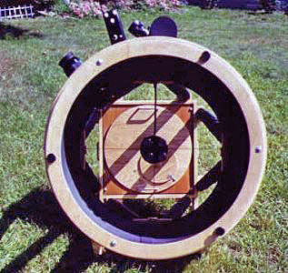
the second coat. On the bottom side of the mirror box, I placed a fan assembly. It has an exterior power supply
and a toggle switch. There are 4 major holes underneath the fan, 1 1/2 " in diameter. There are also 21 - 5/16"
holes surrounding the fan for ventilation. The inside of the mirror box is coated with gray primer, then a coat
of Stone Creations black spray paint. It has a very rough texture. I wanted a non-light scattering surface and
this seemed like a great way to do it. Then I sprayed flat black over this in 2 coats. It looks real good.
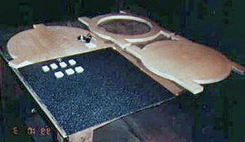
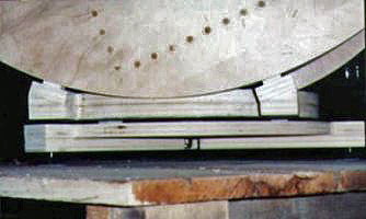
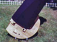
Rocker Box
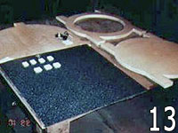
This part of the scope cannot be called a rocker box because it is not a box. It has
practically no height to it whatsoever. The picture will illustrate what it looks like. Photo 13: Top and bottom
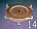
on the rocker plate, Ground board and Ebony star and Teflon during pre-assembly. Photo 14: Completed
Rocker and ground board (no larger photo).
It is essentially a ring, glued to a disk. Both diameters are 16". I did this to maintain
strength but reduce weight. It was cut out with a router and the top ring and bottom ring share the square sides
on which you can discern the Teflon pads which are attached to these square "pads" Now, after I had cut out and
glued and screwed the 2 rings together and doweled, yes DOWELED them together, I clamped them together and let
them dry overnight. I took the rocker (see above), and cut 45 degree angled slots into the squared pads. When
the Teflon in placed onto these pads, the altitude bearings will slide over these. I placed the completed mirror
box over these pads and POOF they didn’t work. The front of the mirror box would not rock over the rocker
because the mirror box was digging into the rocker. I was annoyed to say the least. Then I build up the pads
with blocks so that the mirror box would slide properly over the Teflon and not catch on the rocker. I cut out,
from spare plywood, 1" high by 2 " long by 1 " thick pads, screwed the Teflon onto the pads using the drywall
screws and glued them in place. After I did this, the bearings actually worked, but the previous cuts on the
pads were canted either in or out. I again was annoyed, but after getting some rasps and files, the next evening
I set out to square these off. When I got the results I wanted, I settled for an almost, within .010 of an inch,
squared pads on which virgin Teflon sat waiting to bear the weight of the mirror box.
Ground Board
The original design was a spoked rocker box on a tri-spoked ground board. I chose a solid
ground board with three wooden rectangle legs screwed, glued and doweled onto the underside of the ground board,
from the center out to the edge.. Each leg has a ¼ " hole drilled into it with a corresponding 1" hole on the
topside of the ground board. The 1" hole was for a t-nut to be placed into the hole for which a leveling screw
was to be placed. I epoxied the t-nut into the hole and capped the hole with a 1" hole cap found at Home Depot.
In the ZHRB I drilled a 5/8" hole for the pivot bolt that attaches to the ground board. I got the pivot bolt and
Teflon pads from AstroSystems, Inc (AS) in CO . The Teflon with the pivot bolt was pre-drilled to accept the
bolt to pass thru it. The Teflon pads were pre-drilled and counter sunk to accept any type of wood screw. I
placed the Teflon pads on the ground board in 120 degree points about 80% out from the center to insure good
contact with the bottom side of the rocker onto which I glued with contact cement Ebony Star Formica obtained
from AS. You can, however, get Ebony Star at Home Depot: a 2-foot X 4 foot sheet for about $10. Very cheap
compared to what most telescope making supply stores want. After all was said and done, I spray painted the
rocker and the ground board flat black and over coated then them with Helmsman Spar polyurethane from Home
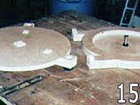
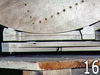
Depot. 2 coats, sanding, another coat of paint and then final coat of Spar was all it took. Photo 15: Rocker
board on the right and the ground board on the left. Photo 16: Mirror box on the rocker board and the rocker
board on the ground board from the side.
Upper Cage Assembly
The upper cage assembly was purchased from AstroSystems. I got a great deal from Alan and
Randy out there. . The upper rings, bars and focuser board cost me $40. I was given the upper clamp blocks for
another $40, saving $30 from the original price of $70 ( I was told they were the last ones so they gave me a
deal), along with the Teflon pads for the rocker and ground board, 2 sided tape for the Kydex light shroud and
the Truss tubes (6061-T1 aluminum at .049 thickness, 1" outside dia.), Phase 4 focuser that cost me $150, (but
have since replaced it with a gleaming polished aluminum focuser from Moonlyte), spider and diagonal holder and
a collimating tool. The spider and diagonal holder will accommodate a 2.6" ma secondary mirror. The original
Coulter secondary was a 3.1", too big of an obstruction, about 26 –28%. The smaller size will reduce that to
about 20%.
I assembled the cage in one evening. The focuser was a little tricky, trying to get it as
close to the inside of the ring yet leave enough space so the Kydex didn’t touch it. I had to cut the support
blocks for the focuser in a semi-circle, using the inside ring as a template to get the right radius. I then
attached the upper clamp blocks, setting them so that the center of the tubes, when placed in the clamps, would
be just outside the center of the middle of the lower ring. The thick aluminum that came with the clamp blocks
was unworkable, so I cut out from thin aluminum sheet using tin snips, the pads in which will take the brunt of
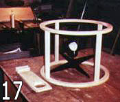
the ends of the tubes when placed in the clamps and will not destroy the wood ring underneath. Photo 17: Upper
cage assembled before installation of the Spider, Diagonal holder and focuser board (No larger photo
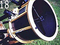
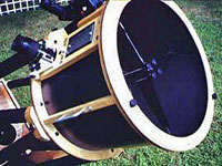
available). Photo 18: A look at the
upper cage assembly. Note the Spider adjusting screws.
After the construction, I stained the wood with 2 coats, as opposed to the mirror box with just one. The
upper cage was made from appleply plywood. It has about 9 – 13 layers and is very light. The Baltic Birch is 5
layers and quite dense and slightly more heavy than the appleply. I applied 2 coats of polyurethane, sanded
after the second and sprayed a third coat. After the overcoat was dry, I applied contact cement to the inside of
upper ring and lower ring and the cage supports. When I set the 2-sided tape to the rings, the contact cement
adhered to the tape and made a tighter seal. The Kydex was placed on the inside of the rings, adhering to the
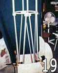
tape creating a light shroud. The Kydex is glossy on the outside and rough and flat on the inside. Photo 19: A
pre-assembly picture, showing the tubes on the inside. Later I opted to place them on the outside.
This part was tricky. I didn’t have any plans or drawings for these parts. There were no affordable
alternatives, as most dealers didn’t sell these separately. I asked AstroSystems for help and they said to drill
holes in the tubes and then attach them to the outside of the mirror box. I didn’t want to drill holes in the
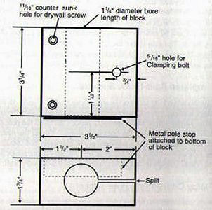
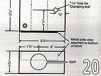
tubes, let alone in the mirror box. Photo 20: Lower clamp block drawing.
As the drawing shows, it is a simple compression block using ¼ - 20 socket head screws, with
plastic knurled knobs attached to the screws with epoxy. My block is 3" wide, 2.5" high and 1.5" thick. It is
made from gluing 2 pieces of plywood together. I drilled a 1" diameter hole using the drill press for accuracy
down thru the block. Then off to one side I drilled a ¼ - 20 hole in which the knob would tighten the block and
produce the necessary tension to hold the tubes in place. I had to make 8 of them, but I made a few extras just
in case. I am glad I did. On the other side of the ¼ - 20 hole is a 1" counter sunk hole in which I placed a
t-nut and epoxied it to the block. The slot in the block was made using the table saw set at the height at which
it intersected the 1" hole for the block to the mirror box in 8 places. I used 2" wood screws for one spot and 1
½" in another; the side that is closer to the tube uses the longer screw, but where the slot is cut in the
block, I used the shorter screw which does not attach to the block until it hits the lower part of the slotted
block. Whew! Rather than the 4 holes in the drawing, I opted for just 2, just in case I had to re-position the
block, based on the angle that the tube was set at to meet up with the upper clamp block.
Now the lower block, attached to the mirror box has 2 angles that have to be used for the
tube to reach the upper clamp block without too much bending. One angle is the tube canted inwards towards the
wall of the mirror box heading up towards a point at the upper cage block. Imagine a straight line drawn from
the point at which the mirror box ends and then intercepts the upper cage. Now imagine the tube running from the
lower clamp block up to the upper clamp block. The next angle is the angle at which the tube is canted towards
the center of the mirror box, but ends at an almost point where the 2 tubes on each side of the mirror box meet
to align with the upper clamp blocks. This compound angle is difficult to set until you are ready to attach the
truss tubes and align them with the upper cage assembly. Then you have to determine the focus of your eyepieces
and probably have to re-align the blocks again to set the proper distance from the primary mirror and the
focuser. As with the mirror box, I sanded them, coated once with the stain, polyurethaned 2 times, sanded after
the 2nd coat and applied a 3rd coat after that. This next picture shows the blocks in place on one side of the
mirror box.
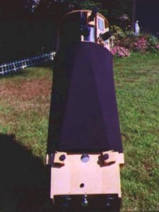
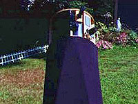
Breakdown
After an evening of deep sky observing, this scope is a breeze to breakdown. I can have the
scope stored in my truck in 5 minutes or less. After putting away all my gear, I can be broken down and hit the
road in 10 minutes. This scope is very easy to store in my apartment. I usually store it assembled, so I can
look at it and make any adjustments or improvements while I look at it. If I choose to store it, ready for
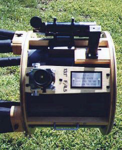
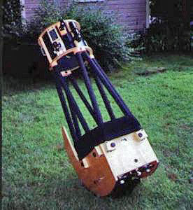
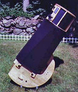
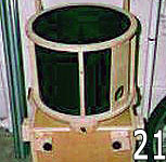
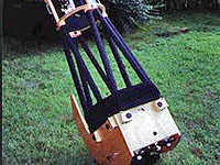
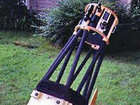
travel this is what it looks like. Photo 21: 'Scope ready to go!
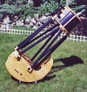
As time went on after I built the scope, I added counterweights to the bottom of the mirror box after first
experimenting with virtual counterweights using door springs. The weights offset the 8 X 50 finder, Kendrick dew
remover system with dew removers on the finder objective and eyepiece, a Rigel quik finder, my use of heavy
eyepieces such as Naglers and the solar filter I have built in a separate cover. The remaining photos show the
scope with the extras added on in its full glory!
This telescope was displayed in the
mechanical competition at
the 2000 Stellafane convention and additional photos can be seen there.
|